Hi Everyone,
I've started building a Full Bridge UcD based amplifier, but I'm having troubles getting the darn thing to oscillate...
I've searched the forums extensively and was able to find two useful threads, but I'm still not over the finish line.
http://www.diyaudio.com/forums/clas...d-amp-full-h-bridge-single-supply-50-v-5.html
http://www.diyaudio.com/forums/class-d/132081-single-supply-bridge-ucd-referencing-signals-9.html
Control Systems Theory is definitely not my strong point so I haven't the slightest clue as to what I'm doing incorrectly.
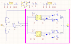
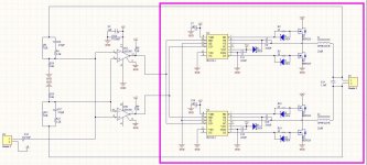
Attached is a schematic - does anyone have any ideas?
Thanks in Advance!
Rachael
I've started building a Full Bridge UcD based amplifier, but I'm having troubles getting the darn thing to oscillate...
I've searched the forums extensively and was able to find two useful threads, but I'm still not over the finish line.
http://www.diyaudio.com/forums/clas...d-amp-full-h-bridge-single-supply-50-v-5.html
http://www.diyaudio.com/forums/class-d/132081-single-supply-bridge-ucd-referencing-signals-9.html
Control Systems Theory is definitely not my strong point so I haven't the slightest clue as to what I'm doing incorrectly.
Attached is a schematic - does anyone have any ideas?
Thanks in Advance!
Rachael
Attachments
Hi Everyone,
I've started building a Full Bridge UcD based amplifier, but I'm having troubles getting the darn thing to oscillate...
I've searched the forums extensively and was able to find two useful threads, but I'm still not over the finish line.
http://www.diyaudio.com/forums/clas...d-amp-full-h-bridge-single-supply-50-v-5.html
http://www.diyaudio.com/forums/class-d/132081-single-supply-bridge-ucd-referencing-signals-9.html
Control Systems Theory is definitely not my strong point so I haven't the slightest clue as to what I'm doing incorrectly.
Attached is a schematic - does anyone have any ideas?
Thanks in Advance!
Rachael
Why did you do a full bridge why didn't you start with a simple half bridge Just curious ???
Reactance,
I really enjoy electronics and pushing myself to understand new things.
My first amplifier was a split supply UcD, my second amplifier was a triangle based amplifier based on the "Thunderball" design posted here:
Class-D amplifier
I wanted to try out a full-bridge UcD as I've read about the many advantages a self oscillator has over a carrier-based design.
Thanks!
Rachael
At the very least you will need a 1k resistor from P2 of U8 to 0V to balance the NFB paths and to set the dc voltage at the comparator. Check also that your audio input is dc coupled, or else P3 of the LM311 will also have a dc bias problem.
Reactance,
I really enjoy electronics and pushing myself to understand new things.
My first amplifier was a split supply UcD, my second amplifier was a triangle based amplifier based on the "Thunderball" design posted here:
Class-D amplifier
I wanted to try out a full-bridge UcD as I've read about the many advantages a self oscillator has over a carrier-based design.
Thanks!
Rachael
I myself is no expert,
I admire your interest but your diagram is riddled with many many issues im not sure how you got to the calculated component values??, the missing input bias, HF compensation, Dead-time control, level shifting etc...
Here is some help. This is a rare hard to find article on the net (how self oscillating class-d amplifiers work its better than the published UCD papers as it actually explains why the lack of detail is deliberately minimalistic and actually has simulations stepping through and explaining each switching node)
To be honest no one here is going to give you a robust circuit its like a gold rush as majority of some members are trying to mine knowledge and sell kits on ebay and the likes. (with some even failing hopelessly and throwing a fit unable to solve and reach their goals 😀 )
Self Oscillating Class D
Last edited:
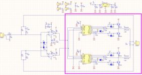
Jpg from data sheet.
With 15V supply the input threshold is 9.5V.
With 12V supply the input threshold is probably between 7v and 8V.
5V drive will probably not work.
Put some diode clamping in the input lines for protection.
Look at open collector (drain) drivers and pull-up to 12V.
🙂
With 15V supply the input threshold is 9.5V.
With 12V supply the input threshold is probably between 7v and 8V.
5V drive will probably not work.
Put some diode clamping in the input lines for protection.
Look at open collector (drain) drivers and pull-up to 12V.
🙂
Attachments
If you really want the amp to run from a single +ve rail, then using two IRS20124 gate drivers instead of the IR2110 gives you the advantage that you get programmable dead time and also standard 5v or 3.3V input logic thresholds. You really need a way to get ordinary ac-coupled inputs into your comparator stage. Using a 24V supply, your comparator inputs (if you add the 1k to ground as mentioned before) will self-bias at 0.52V if the amplifier is oscillating at idle, and you really need an input level shift stage to sum-in the nfb.
I have done this very succesfully some time ago using a PNP differential pair with a current source in the emitter line, feeding two resistive loads to 0V, with the collectors of the differential stage feeding the + and - inputs of the comparator.
I have done this very succesfully some time ago using a PNP differential pair with a current source in the emitter line, feeding two resistive loads to 0V, with the collectors of the differential stage feeding the + and - inputs of the comparator.
Sorry for my previous partial post.
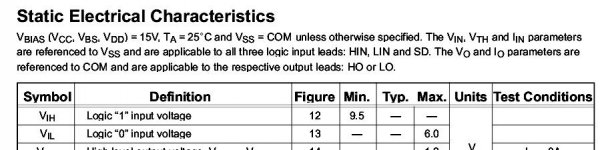
I've attempted to modify my circuit based on all the advice you have posted.
Right now I believe my biggest problem seems to be getting the DC bias to a level where I can couple an AC signal to the comparator.
Is the circuit I've attached going to work or am I still out of line ?
Thanks,
Rachael
I've attempted to modify my circuit based on all the advice you have posted.
Right now I believe my biggest problem seems to be getting the DC bias to a level where I can couple an AC signal to the comparator.
Is the circuit I've attached going to work or am I still out of line ?
Thanks,
Rachael
Attachments

Change R10 to 10K so that the feedback thresholds within the range of the comparators.
Add a corresponding resistor to the other feedback path so they are symmetrical.
Then you will not need the diodes.
🙂
Add a corresponding resistor to the other feedback path so they are symmetrical.
Then you will not need the diodes.
🙂
Hey Everyone,
I had a chance to work on this project over the weekend and I finally got it to oscillate!
I had to do two things:
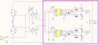
1. Following DUG and Ouroboros ‘s advice I’ve added 10K resistors from both the inverting and non-inverting comparator inputs to ground.
2. I had to move the comparators GND1 [Pin 3] and GND2[Pin 8] from +6V to GND.
I just wanted to thank you all again for your help!
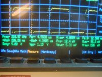
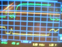
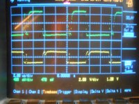
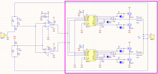
I’ve attached some pictures of the latest schematic, prototype implementation and waveforms of both the high and low side gate drive signals.
I still have a few more questions.
Will coupling an Audio signal into this circuit be as straightforward as I have drawn in the schematic above?
I see a slight glitch in the Gate Drive signal. I’m guessing this is due to my poor layout. Am I correct about this assumption or is this the sign of me doing something else wrong?
Thanks!
Rachael
I had a chance to work on this project over the weekend and I finally got it to oscillate!
I had to do two things:
1. Following DUG and Ouroboros ‘s advice I’ve added 10K resistors from both the inverting and non-inverting comparator inputs to ground.
2. I had to move the comparators GND1 [Pin 3] and GND2[Pin 8] from +6V to GND.
I just wanted to thank you all again for your help!
I’ve attached some pictures of the latest schematic, prototype implementation and waveforms of both the high and low side gate drive signals.
I still have a few more questions.
Will coupling an Audio signal into this circuit be as straightforward as I have drawn in the schematic above?
I see a slight glitch in the Gate Drive signal. I’m guessing this is due to my poor layout. Am I correct about this assumption or is this the sign of me doing something else wrong?
Thanks!
Rachael
Attachments


Actually, I was going to comment that when you attach an audio source to the input it will negate the feedback drive into the top comparator.
Consider the feedback not even there and analyze your circuit again.
Consider the feedback not even there and analyze your circuit again.
DUG,
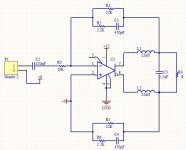
I've looked at the design without feedback and I think I sort of understand what you're saying. I need to come up with a biasing scheme on the comparator input where the Audio signal can swing in both a positive and negative direction with respect to that bias voltage.
Are my latest schematics any closer to the mark?
Thanks!
Rachael
Attachments
Thank you for your replies DUG and savu!
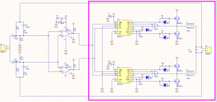
After reading through the thread savu pointed out I think I've come up with two solutions.
A differential and single-ended version.
The way I calculated my bias was to assume a 24-volt supply and use the resistor divider equation to get +6volts of bias [1/2 of the comparators supply voltage) on both inverting and non-inverting comparator inputs hence 10K and 30K.
Do I finally have it figured out?
Thanks!
Rachael
Attachments
- Status
- Not open for further replies.
- Home
- Amplifiers
- Class D
- Need help with Full Bridge UcD Feedback Loop