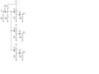
Hi! I wonder which jfet should be more suitable as a source follower (therefore unity gain) in the signal splitter on the drawing in attachment? I'm using at the moment J201 but have never tried any other type (like BF245 or 2SK130, ......). I've read somewhere that sonically it doesn't really matter which one I use as a source follower, or does it?
It also doesn't matter the output current because I can always put in parallel (see attachment) the outputs and get more current in case needed.
I guess they have to matched to get the best result. Is there a special procedure to do the matching or it's just a matter of comparing the resistance between the gain, drain and source?
Attachments
You wont need to match FETs for any application like this (proper matching involves plotting and comparing the Drain current vs Gate voltage). Nothing to be gained (imo) by using other types.
Biggest failings of the circuit are the 10k resistive source load and the limited output drive ability that brings. Using 9 volts is a big limitation too.
Biggest failings of the circuit are the 10k resistive source load and the limited output drive ability that brings. Using 9 volts is a big limitation too.
Ok. Can you explain why and what would to be changed (apart from the 9V, which is obvious and I will use 15V or even 18)?
Thanks
Thanks
There are several things you've not taken into consideration (which DOES impact which FET you decide to employ)
[1] Vgs(off) voltage
[2] Vgs(nom) voltage
These are related, of course. The J310 (20 mS transconductance), as a Vgs(off) typically around 5 volts, and in operation with say 5 ma as the design point, 3 volts for Vgs(nom).
So, you need to work that backward: E = I R ... R = E / I, where E = 3.0 volts and I = 5 ma. R = 600 ohms ... this would be the "R" for the source, replacing the 10K you have listed.
OK, so its about 3 volts. If you want the maximum range (which kind of obviously is set at the half-point of V+), then you need to SUBTRACT that 3 volts from 1/2 V+, to get the operating bias of the gate. So, say V+ = 18V. 1/2V+ = 9V. 9V - 3V = 6V. What gate bias resistor-voltage-divider pair gives that from 18V? 6V/18V = 1/3. R2 = 2M, R3 = 1M... Now we're talking.
Lets look at that source load resistor again. DeltaV between source and ground is (designed to be) 1/2V+ = 9V. we again are searching for 5 ma of current flow ... E = IR, R = E/I = 9/5ma = 1,800 ohms. Cool! Same basic design point, with a gate bias of 6 volts.
Thus the "napkin calculation" of operating points. This will result in better load driving ability, too. The Thevenin equivalent resistance (input impedance) of the gate is ... (2 x 1)/(2 + 1) = 660 kOhm ... which is nice and high. The R1 of 10,000K might depress that another 10% [well, actually (0.66 * 10)/(0.66 + 10) = 0.62M] but still, quite high input impedance.
I too recommend 18V supplies for this. Conveniently, this could be a pair of conventional square-can 9v batteries.
PS: I wouldn't set the design point much below 2ma for the J309/J310 family ... for reasons of linearity and getting into the steep part of the transconductance curve. FETs have their sweet spot, "manufactured in" so to speak. At $0.30 apiece (Mouser), they're an awfully good deal. I've used the J310 series VERY successfully in creating built-in preamps in acoustic-magnetic pickup Irish harps. Very nice sound - sweet, clear, without hollowness or boominess.
That should do you. The rest of the circuit - is just fine.
GoatGuy
Hi GoatGuy!
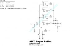
To tell you the truth I did not design this. It's AMZ splitter from Jack Orman at Guitar Effects Pedals, Schematics, Stompboxes & Electronic Projects, but even though it has been made for guitar effects it suited nicely my purpose for audio splitter. There is also mentioned that in case the sound is a little too harsh or too soft, the R2-R3 could be changed up to10M to get the proper sound as long as we keep them (R2, R3) equal, which i understand.
So you suggest to use the 18V as power source and then the 10k resistor would be ok there?
No... maybe you need to read what I wrote, again.
RECOMMENDATIONS:
Supply: 18 volts
R4, R6, R8: 1.8K ohms
R2: 2.2 megohms
R3: 1.2 megohms
or if you prefer
R1: 10 meg
R2: 4.7 meg
R3: 2.2 meg
for input impedance of (1/(1/10+1/4.7+1/2.2)) = 1.3 meg
THESE values are tuned for the J310, for 18 volt supply, to allow maximum input levels of ∓ 7.0 volts, peak-to-peak (without appreciable distortion). Moreover, for normal "line level" input (from 0.6V to about 2.0V) there is virtually no distortion, period.
Got it? RE-READ what I originally wrote, and please try to understand the math a bit. IF... you don't, and want help understanding electronic math, I may have time to give you some pointers. But until you ask, I'm assuming you either know Ohm's law, Thevenin's equivalences, what transconductance is, and the basic operation of an FET.
Yours,
GoatGuy
A great answer from GG for you there...
and what I would suggest you do is write down your own specifications. What sort of load will each output drive ? Is it battery powered ? that's important, a couple of milliamps three times over will soon discharge 9 volt batteries if it gets a lot of use.
If the load impedance were 10K then you might sqeeze around 4 volts RMS output into 10K running 15 volt supplies with the fet running at around 2ma. Although we think of this as a buffer, the output is around 1db down in amplitude compared to the input.
The concept of an "amplifying buffer"
One concept that I've quite successfully employed is the notion of a buffer that has just a bit of amplification. Very little ... 1dB to 3dB.
Its one of those circuits you hardly ever see these days, but its still good.
Basically, you use a higher voltage power supply (in this case, 24 to 30 volts). The voltage divider to establish gate bias is set to 1/8th V+, or 3 volts. (suitable resistors in this circuit would be 6.8M for R2 and 1.0M for R3).
Again, with a 5 ma design point, and a 3.0 volt bump up of source over gate, source V = 3 + 3 = 6.0 volt. E = I R ... R = E / I = 6 / 5ma = 1.2k ... great!!! Now... for say 2 dB gain (over the slight buffer loss, yielding like 1.5dB final gain), just multiply 1.2k ohm by (10^(0.2)) = 1.901k ; any resistor reasonably close will do (unless you are doing this in stereo, in which case MATCH the resistors well!)
The drain-side resistor of 1.9k gives 1.58x gain (2dB) over the source resistor's "buffering" (non-amplification / signal tracking). The output impedance is a bit higher, but you get some gain too ... and because of Ohm's law ... and no reactive devices being used to shape the response of the thing, the output is darn clean.
This idea is the "secret" behind an in-tip preamp that I made for connecting passive-pickup guitars, or piezo pickup devices to sound boards. Looks like a mike cable on the 'board' end, but has a phantom-powered pre in the top of a quarter-inch plug at the other end. Truly amazing, running guitars, harps and fiddles through a quality mic preamplifier on a sound-board.
There you are.
GoatGuy
@GoatGuy:
I cannot thank you enough for the explanation given. I had to re-read your first post a few times, but now I understand what you mean. I know well Ohm's law, but much less the Thevenins equivalences...but I get your point now, so thanks again!
@Mooly: my thanks goes to you as well!
I cannot thank you enough for the explanation given. I had to re-read your first post a few times, but now I understand what you mean. I know well Ohm's law, but much less the Thevenins equivalences...but I get your point now, so thanks again!
@Mooly: my thanks goes to you as well!
Oh, I forgot...my power supply will probably be regulated with a low dropout voltage regulator, which should do the job.
One concept that I've quite successfully employed is the notion of a buffer that has just a bit of amplification. Very little ... 1dB to 3dB.
Its one of those circuits you hardly ever see these days, but its still good.
Basically, you use a higher voltage power supply (in this case, 24 to 30 volts). The voltage divider to establish gate bias is set to 1/8th V+, or 3 volts. (suitable resistors in this circuit would be 6.8M for R2 and 1.0M for R3).
Again, with a 5 ma design point, and a 3.0 volt bump up of source over gate, source V = 3 + 3 = 6.0 volt. E = I R ... R = E / I = 6 / 5ma = 1.2k ... great!!! Now... for say 2 dB gain (over the slight buffer loss, yielding like 1.5dB final gain), just multiply 1.2k ohm by (10^(0.2)) = 1.901k ; any resistor reasonably close will do (unless you are doing this in stereo, in which case MATCH the resistors well!)
The drain-side resistor of 1.9k gives 1.58x gain (2dB) over the source resistor's "buffering" (non-amplification / signal tracking). The output impedance is a bit higher, but you get some gain too ... and because of Ohm's law ... and no reactive devices being used to shape the response of the thing, the output is darn clean.
This idea is the "secret" behind an in-tip preamp that I made for connecting passive-pickup guitars, or piezo pickup devices to sound boards. Looks like a mike cable on the 'board' end, but has a phantom-powered pre in the top of a quarter-inch plug at the other end. Truly amazing, running guitars, harps and fiddles through a quality mic preamplifier on a sound-board.
There you are.
GoatGuy
I can well believe it sounds great, but isn't that just a common source configuration ? Inverting of phase.
Maybe I'm misunderstanding you 🙂
I suppose its for guitar
and for driving multiple effect pedals
and those will have hi-z input ?
why not use gain stages for splitting instead ?
is there a complete preamp layout schematic ?
and for driving multiple effect pedals
and those will have hi-z input ?
why not use gain stages for splitting instead ?
is there a complete preamp layout schematic ?
Yes, it's for a guitar amp, but I guess the same principle could be used for audio purposes by adjusting the values of components.
Initially I was thinking of having a sort of analog splitter or "interstage trafo" made with tri-filar windings so that whatever happened in the first winding it would be happening the same in the others...this was my initial idea until I found that schematics using J201. What i liked is that one can add as many outputs as one wants...this could serve for testing the sound of various amps with the same signal or possibly achieving different (new) sounds using many different amps at once...
If anybody has any different idea (for guitar amp as well as for audio amps) to achieve the same result I would be glad to hear it.
Last edited:
The simple jfet circuit, whatever its limitations, will always sound "pleasant and musically pleasing". This is because the distortion is relatively high and predominantly second harmonic.
If you went down the other route of using opamps then you may well lose that added "musicality". Technically, the opamp would be superior in that it would have much better dive ability and the output would not be affected by loading (within the opamp limits).
Ultimately the simple FET solution may well be the best for your use.
matej8888;3543503...this could serve for testing the sound of various amps with the same signal or possibly achieving different (new) sounds using many different amps at once...[/QUOTE said:waste of time
its easier to just switch connector
anyway, if you want it as pre out for driving power amp, I would suggest to have only one buffer, and focus on quality instead of quantity
@Mooly: correct, opamps were an option as well...there's even almost the same circuit using TL072, but I somehow prefer Jfets... I can post also the schematics with opamps if anybody wants?
@tinitus: you mean a nice powerful tube buffer and then split the buffer output between the amps?
Yes, I understand you when you say about using switch connector, but I intended using all amps at the same time and not switching among them.
So the "interstage transformer" is a bad idea?
@tinitus: you mean a nice powerful tube buffer and then split the buffer output between the amps?
Yes, I understand you when you say about using switch connector, but I intended using all amps at the same time and not switching among them.
So the "interstage transformer" is a bad idea?
Try attaching images directly 🙂 That is the longest URL I have seen, three pages of this 😀
To add a photo, files or non standard files.
First click "go advanced" in the box below the "quick reply" message box. Doesn't matter if you decide half way through a message to do that, it carries it forward.
Then click "Manage attachements". Maximise the new Window so that you can see all the text.
Click browse in the first box at the top and find your picture. Repeat for any more pictures.
Click upload... a message appears "uploading"
When complete the files will show as being attached. Now click the small text that says "close this window"
The pictures should now be attached and when you submit your post they will appear.
Make sure your pics aren't too big, a couple of 100k is plenty, and many members object when they are massive and it alters the margins
It tells you in the attachments window what max sizes are allowed.
If you want to attach a file that has a non standard format for example excel, circuit simulation etc then try putting the files in a zipped folder and attaching that.
Attachments
No problem 🙂
So that's placing opamps in parallel to get even more drive ability. Its a valid technique if you really that much drive ability.
You could also use a single quad opamp (TL074 etc) and have each of the three opamps as an isolated feed, still with far better drive ability than the FET. With opamps there are many possibilities.
- Status
- Not open for further replies.
- Home
- Design & Build
- Parts
- which jfet for signal splitter