I suppose it depends on the power supply, and on what you call "minimal". I would say, none noticeable in my current setup. Sakis may be able to give a more general answer if he sees this post, I can only comment on the one example I built. I have an idea why, but have not really investigated that aspect much.PMI - I'm surprised P3A is thump-free as it uses bootstrap VAS, why is it thump-free ? I checked Rod's web site and he says 'minimum' noise so I take it there is some noise so I put in the 2nd list for now...
Member
Joined 2009
Paid Member
my alephs dont have any that i remember..... its summer so i havent tryied them in a bit....
sounds like you have an excuse to fire them up 😀
I suppose it depends on the power supply
what kind of precautions do you take in the power supply ?
Thumps because of the power supply? NO WAY!!! I have try many amps using SAME power supply and some had this problems and some did not!...so it is all in the design of the amp.
Design must take care of fast settling of the DC operating
conditions as well as an eventualy slow ramping PSU
that could slow down said settling and maintain the circuit
in non linear operation for a time long enough that earratic
output voltage can occur at the output due to non functionality
of a part of thev circuit.
conditions as well as an eventualy slow ramping PSU
that could slow down said settling and maintain the circuit
in non linear operation for a time long enough that earratic
output voltage can occur at the output due to non functionality
of a part of thev circuit.
Member
Joined 2009
Paid Member
From what I've seen of my own TGM1 amplifier (simulations mostly) there is a time lag to charge up the feedback shunt capacitor. Whilst that happens, the feedback loop tries to correct a dc offset that isn't really there. And with a VAS bootstrap, that cap has to be charged up too. Both affects happen at the same time and depending on the values of the components the turn-on thump can be all sorts of different shapes.
You can add the sx-Amp to you list.
In fact, I challenge any amp, including ones with speaker muting on power up (the sx-Amp does not have any speaker muting circuit or relay) to a power up thump contest.
In fact, I challenge any amp, including ones with speaker muting on power up (the sx-Amp does not have any speaker muting circuit or relay) to a power up thump contest.
Member
Joined 2009
Paid Member
@Bigun: This is the kind of discussion that is likely to derail your thread, but here goes:what kind of precautions do you take in the power supply ?
My own goal for power supplies is that they should not contribute or change 1) what you hear at the output of the amp, or 2) see on an oscilloscope within the audio range. The amplifier circuit should not be called on to remove crap on the output of the supply. If the power supply produces artifacts which turn into a DC offset disturbance at the output of the amplifier, you will hear a thump, or a buzz, or a squeak from the speaker, regardless of the amp... GIGO (garbage in, garbage out).
If I hear nothing with my linear bench supply, and something else with the intended supply, I can conclude the noise is caused by the supply.
Only precautions with the P3A was to make sure that my power supply decayed cleanly, and did not contribute any big disturbances on turnoff. (Simple compared to some of my other efforts.)
In regard to the P3A build as described on the ESP web site, and using my old linear bench supply for comparison testing, I found no contribution to any turn-on or turn-off thump, or any other noise from the amplifier itself. None, zero. None audible within a foot from my ear to the speaker, and only a tiny disturbance visible on the scope, when the power supply voltage had decayed to a very low level.
Only deviation from the basic directions is that I used a very rough match on the input transistors (also recommended by Sakis and others), and I added an extra 100uF capacitor when I cut the boards apart to separate the two channels, also as described somewhere on ESP. This was the case even before I made some of the component changes suggested by Sakis in other threads here.
With the rectifier/filter as recommended on the web site, a tiny amount of noise, on turn-off only, more like a quiet click, but a bit more with the source playing. And after working on the power supply a bit (better rectifier diodes, CLCRC filter and tweaking the resistors used to discharge the caps on turn-off), no noise, same as the bench supply. No beer cans btw, and no "LAIC" (large array of inexpensive caps). 3x4700uF per rail, bought for $1.25 each from Dudaindc here. and even that is overkill. Inductors from the parts bin, and a couple used power resistors from a bag of junk purchased on ebay.
I should add that I tend to modify my power supplies to fit the amp or whatever else is connected to them, and most people will not want to do that. My latest effort is to build a linear supply which is a good match for two of the other projects you listed above, VSSA and my version of PeeCeeBee. Not using recycled parts this time, 😀 (still working on that one... )
Member
Joined 2009
Paid Member
I don't think you are derailing the discussion at all - the more knowledge the better. I like the idea of comparing with a bench supply.
Just to clarify though - how quiet is your P3A at turn-on, given that caps inside the amp have to charge up did you need to size parts to minimize issues or were parts sized for frequency response and in conflict with what is needed for small turn-on noise ?
Just to clarify though - how quiet is your P3A at turn-on, given that caps inside the amp have to charge up did you need to size parts to minimize issues or were parts sized for frequency response and in conflict with what is needed for small turn-on noise ?
100% quiet on turnon. 99% quiet on turnoff. I only changed my own supply, nothing on the P3A boards, except this:Just to clarify though - how quiet is your P3A at turn-on, given that caps inside the amp have to charge up did you need to size parts to minimize issues or were parts sized for frequency response and in conflict with what is needed for small turn-on noise ?
The P3A board as sold on ESP is two channels on one board. As such has a total of two 100u decoupling caps, one per rail shared for both channels. It can be built and used as is, one board.
It can also be cut in half, to mount separately. When I cut the boards in half, I added a 100uF cap to each one, to restore identical caps on each rail on both boards. (It is simpler than it sounds). I can post a pic later or tomorrow, if you like.
dynakit ST120 is silent both as designed, with TIP mod, and with djoffe cold bias mod http://www.diyaudio.com/forums/solid-state/156627-dynaco-stereo-120-can-beautiful.html
Schematics are freely available but they are bankrupt, you have to build the boards point to point. And find your own power transformer. Speaker DC protection is inherent in the design without relays or complicated detection circuits, which is why I fool with them. also low parts count. With the cold bias mod it sounds good. They are pretty low tech on semiconductors- I'm using MJ15015, TIP41-42, MPS8099. Need cooling fan to stabilize temperatures, no constant current sources to up the parts count.
Schematics are freely available but they are bankrupt, you have to build the boards point to point. And find your own power transformer. Speaker DC protection is inherent in the design without relays or complicated detection circuits, which is why I fool with them. also low parts count. With the cold bias mod it sounds good. They are pretty low tech on semiconductors- I'm using MJ15015, TIP41-42, MPS8099. Need cooling fan to stabilize temperatures, no constant current sources to up the parts count.
Last edited:
Member
Joined 2009
Paid Member
100% quiet on turnon. 99% quiet on turnoff. I only changed my own supply, nothing on the P3A boards, except this:
The P3A board as sold on ESP is two channels on one board. As such has a total of two 100u decoupling caps, one per rail shared for both channels. It can be built and used as is, one board.
It can also be cut in half, to mount separately. When I cut the boards in half, I added a 100uF cap to each one, to restore identical caps on each rail on both boards. (It is simpler than it sounds). I can post a pic later or tomorrow, if you like.
Well I'm impressed and even more curious. I don't want ask you violate Rod's IP but can you at least say whether the version you built, topology and parts values, is wildly different from what he has posted on his website or if you think it's close enough not to be relevant for this discussion ?

No need to violate Rod's IP agreement, because my comments are about the version I built according to the directions, which include the option for separating the board into two helves. Only other changes were, addition of a single 100uF cap on each board, and fuses left off the boards, because the power supply I used was already fused at the output.Well I'm impressed and even more curious. I don't want ask you violate Rod's IP but can you at least say whether the version you built, topology and parts values, is wildly different from what he has posted on his website or if you think it's close enough not to be relevant for this discussion ?
Everything I said applies to the boards as they were before I started to make component substitutions suggested by Sakis and other changes. Even after that, only changes I made are what has already been discussed and documented in this forum by others. No hard-to-get transistors, no fancy caps, modest input caps, no pixie dust.
Renardson MJR7
The Renardson MJR7 has anti-thump circuitry. A very well-documented and tested design.
MJR7-Mk5 Mosfet Power Amplifier
The Renardson MJR7 has anti-thump circuitry. A very well-documented and tested design.
MJR7-Mk5 Mosfet Power Amplifier
Member
Joined 2009
Paid Member
The Renardson amp says it has a small turn on noise - so I put it in the 2nd list - but anybody with direct experience can say it's inaudible ? The circuit technique to reduce the turn on thump is a good one to remember, it limits the drive voltage to the output push-pull pair to a diode-drop when first turned on, but then 'gets out of the way' once a local cap is charged up.
I notice that the Leach amplifier says " The diff amps use resistive tail current bias circuits. Not only do these generate less noise than active current sources, but they provide a smooth amplifier turn-on that is free of thumps." yet P3A has a current source tail. ?
I notice that the Leach amplifier says " The diff amps use resistive tail current bias circuits. Not only do these generate less noise than active current sources, but they provide a smooth amplifier turn-on that is free of thumps." yet P3A has a current source tail. ?
Last edited:
@Bigun: I reassembled my "experimental" VSSA/PeeCeeBee chassis with the P3A boards last night so I could check for any "thump" again, and I do not hear any. There is a slight click, audible only from a few inches away from the speaker. So I guess we can't call it absolutely quiet.
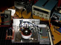
I still think it is the supply, at least in this case, because there is no sound whatsoever with the bench supply.W ith the original supply shown below, there was a small amount of noise. With the second supply, almost none, with the bench supply, zero.
The first picture is pretty close to how I tested. Original power supply with bridge rectifier and filter caps on the left. Transformer and second version of the power supply in the middle. P3A boards on the right side, mounted to a single heatsink.
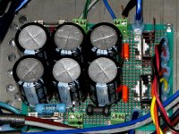
Second pic is the power supply I am using with the P3A now.
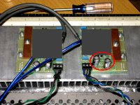
Third pic shows how the two capacitors are mounted on the board now.
I edited out the part of the board which is relevant to the P3A circuit, so hopefully I won't upset anyone this time... well, not too much, anyway.
🙄
I still think it is the supply, at least in this case, because there is no sound whatsoever with the bench supply.W ith the original supply shown below, there was a small amount of noise. With the second supply, almost none, with the bench supply, zero.
The first picture is pretty close to how I tested. Original power supply with bridge rectifier and filter caps on the left. Transformer and second version of the power supply in the middle. P3A boards on the right side, mounted to a single heatsink.
Second pic is the power supply I am using with the P3A now.
Third pic shows how the two capacitors are mounted on the board now.
I edited out the part of the board which is relevant to the P3A circuit, so hopefully I won't upset anyone this time... well, not too much, anyway.
🙄
Attachments
Last edited:
Member
Joined 2009
Paid Member
You have a nice bench set up there - we have the same Fluke meter, but you have nice variac and nice solder station - I have just the iron from Home Depot and it rests on the bench top when not being used.
How do find the sound of your P3A now - is it how you remembered, does it give the VSSA a run for it's money ?
How do find the sound of your P3A now - is it how you remembered, does it give the VSSA a run for it's money ?
- Status
- Not open for further replies.
- Home
- Amplifiers
- Solid State
- which DIY amps free of turn on/off thump?