Hi all,
I'm having issues with an I2S bus between a CS8411 and a TDA1543 and I'm absolutely stumped.
Essentially I'm getting a four bit shift somewhere giving an unwanted digital gain. The DAC works fine if I turn my digital source (computer) down to 6% volume and at this point makes full scale, undistorted output.
There is nothing wrong with the output from the computer, I have a second DAC that I can plug in and the output levels work correctly.
I had an identical problem before when I tried to lift the TDA 1543 from the second DAC and feed it with a custom power supply. This DAC uses a DIR9001, and I never managed to fix it so I put it all back to standard, and hey presto it worked fine again.
The part that’s really bugging me is this is a completely new DAC, all new power supplies and new decoder but, exactly the same problem as before.
By deduction it has to be something that I'm doing wrong, but for the life of me I cannot figure out what.
Do you have a 'scope? If so then some phase shift between WS (the L/R framing pulse) and the data could be the culprit. Examine where the data line is changing wrt to the WS signal would be my first step.
I don't have a scope I'm afraid, but this is the same conclusion I have come to. I can't see any other way of the gain occuring.
What the hell have I done (twice in a row now) with the I2S bus to make this happen?
I'm just using some 0.5mm soild core wire from the reciever to the DAC, no longer than 40mm. Although I have cut into the WS line to add in a 33R resitor as other projects I've seen often have used a resistor on the I2S lines, but to no avail.
Since you're getting the same problem with two different setups, what is in common between the earlier case and now? That would be the first port of call to investigate. You changed over from DIR9001 to CS8411 which makes it extremely unlikely the receiver's to blame.
Try your finger on each I2S line. It will not fix this but if the distortion reduce a little bit, then you can use a small cap (1nF) from the signal to ground and distortion may go. Data is most likely for this solution. It is not the technical but the practical solution for some I2S distortion problems. It is safe to try.
Both projects where/are feeding an I2S bus to a TDA1543 using passive I/V and a separate regulated power supply (commoned to the receiver ps).
The TDA chips are different, the power supply layout and topology is different. The only components that are the same are the coaxial input/output terminals and the toroidial transformer for the DAC power supply.
The TDA chips are different, the power supply layout and topology is different. The only components that are the same are the coaxial input/output terminals and the toroidial transformer for the DAC power supply.
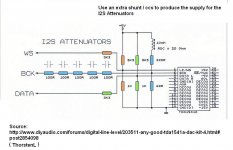
I attach an I2S attenuator that ThorstenL had published.
I don’t know if digital level has to do with your problem.
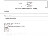
See some important amplitude and timing limits with I2S specifications:
https://www.sparkfun.com/datasheets/BreakoutBoards/I2SBUS.pdf
I really would like to see a few paragraphs explaining what (and how) I have to look for with I2S data transfer, when probing the lines with a scope, something in the form of abraxalito post.
George
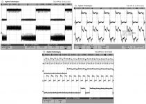
>Edit. My oscilloscope starts dropping above 20MHz (-3db).
Attachments
Last edited:
Nanoloop, I tried adding a little capacitance to ground on the I2S lines, but no change.
The distortion only starts after I turn the digital source over 6%, it's clean and clear, and also much louder than it's supposed to be below 6%. When distortion sets in, it's white noise on the louder samples, exactly what you would expect if the MSBs are cut from the samples, leaving erroneous data.
gpapag, putting an attenuator on the I2S lines had not occurred to me, but I have limited understanding of the effects of digital level on phase shifts and timing across the bus.
Could I try a simple voltage divider attenuator, is it likely to have positive effects and if so what sort of values would be called for?
Are you using the right resistor values for the TDA1543 output and offset? People often get this wrong.
Hi DF96, yeah, I've been over those calcs loads of times. Besides, distorsion is not really the best way to discribe whats happening, its not distorting, its changing from clean, clear music into white noise as the volume is turned up over 6%.
It appears I'm loosing the four MSBs on every sample by virture of a four clock shift on the WS line. AFAIAA the analoge I/V has no effect on the I2S bus?
It appears I'm loosing the four MSBs on every sample by virture of a four clock shift on the WS line. AFAIAA the analoge I/V has no effect on the I2S bus?
Nanoloop, I tried adding a little capacitance to ground on the I2S lines, but no change.
The distortion only starts after I turn the digital source over 6%, it's clean and clear, and also much louder than it's supposed to be below 6%. When distortion sets in, it's white noise on the louder samples, exactly what you would expect if the MSBs are cut from the samples, leaving erroneous data.
gpapag, putting an attenuator on the I2S lines had not occurred to me, but I have limited understanding of the effects of digital level on phase shifts and timing across the bus.
Could I try a simple voltage divider attenuator, is it likely to have positive effects and if so what sort of values would be called for?
I can think of attenuators work by attenuating the low level signal along with the high level one.
As is shown in the specs, there is a requirement for the low level signal to be below a certain value (VL). Else, false triggering and/or false timing occur.
Thus the attenuated low level signal will have the noise riding on it also attenuated , possibly below VL .
IMO, this is a brute force technique, as it attenuates any part of the signal (high, low, noise) by the same percentage. It also may reduce high level signal below VH which is not wanted.
From decades ago, in RF pulse reception (communications and Radar), the problem of noise on pulsed data was treated with base clipping for VL and peak clipping for VH (in essence a Schmitt trigger). Thus apart for proper VL, the sides slope of the signal pulse became stiffer.
Shunting the I2S lines with a capacitor is a LP filtering action. This by careful trimming, may achieve better results than resistive attenuation, provided noise is composed of frequencies >> signal frequencies
George
Attachments
Attachments
You probably already know this (I didn't) but apparently there are different versions of I2S format. See sony-philips-i2s-format-conversion. Could that be the problem?
Thanks for your help George, unfortunately because I don't have a scope I can't tell if there is too much noise on the bus.
DF96, I did not know about the two different versions, that thread made interesting reading.
But, what bugs me the most is the last project I had this exact same problem with. The TDA1543 worked flawlessly on the main board. When moved one inch away, with a new power supply it started all this bad behaviour. I put it back and it worked again. Now I've built my own complete DAC including receiver and all new power supplies and its behaving exactly like before, as if there is a four clock delay on the WS line.
Investigate your grounding and supply rail decoupling. Getting the same problem on different projects suggests you are making the same mistake somewhere.
SPDIF Isolation
Wonder if your using transformer isolation between input receiver and spdif source? Maybe something extra is being coupled in. Ground loop? Just a thought....
Wonder if your using transformer isolation between input receiver and spdif source? Maybe something extra is being coupled in. Ground loop? Just a thought....
Digital signal integrity, sounds like the problem, one design can work perfectly another not at all. What a lot of people forget is that digital signals consist of two parts the hot signal and its return path, both are equally important, both should be considered when designing digital systems.
Termination (or attenuation, not my favourite term for digital) also has to be considered carefully, as impedance, mismatches can again destroy the signal.
Termination (or attenuation, not my favourite term for digital) also has to be considered carefully, as impedance, mismatches can again destroy the signal.
Yep, something is up with the digital bus.
I have recently cut into the grounding/coupling between the two digital circuits, and placed a 1m lead, followed by several values of resistance. My reasoning being that if I can make it worse, I may have a clue how to make it better. It took a 100K resistor and a 1m return path before any difference was noticed. Then it was partially corrupted data at all volume levels, not the constant shift on the WS line (that was still occouring) that appeared to happen.
I have decided that I can go no further without an oscilloscope, and I’m currently looking at second hand units. I’m guessing I need a dual trace analogue one that’s rated at 20MHz or over, but I’m not 100% sure?
Thanks for all your inputs, if anyone has any further suggestions of tests to try out on the bus, I’m more than happy to give them a go?
Have a look at this, its a very informative and explains nicely how critical digital ground (ground planes) is.
http://www.x2y.com/filters/TechDay0...log_Designs_Demand_GoodPCBLayouts _JohnWu.pdf
Henry Otts site also has some good info:
home page
🙂
And one of the masters of signal integrity:
Signal Consulting, Inc. - Dr. Howard Johnson
http://www.x2y.com/filters/TechDay0...log_Designs_Demand_GoodPCBLayouts _JohnWu.pdf
Henry Otts site also has some good info:
home page
🙂
And one of the masters of signal integrity:
Signal Consulting, Inc. - Dr. Howard Johnson
Nanoloop, thanks for this hint - 1pf caps on the data and bclk line didn't completely eliminate the distortion, but made them much better.
Whats the theory behind this?
Whats the theory behind this?
- Status
- Not open for further replies.
- Home
- Source & Line
- Digital Line Level
- I2S problems