Hi all,
I'm doing some work now on an amp that had its transformer's thermal fuse burnt due to voltage surge and spikes of 250Vac while the amp must operate on our 230Vac mains.
So, while my dim bulb tester is not yet ready to see if there's a short in the transformer's primary, I was thinking of a very efficient, stable, steady and fully protected power supply to feed smoothly and continuosly a circuit without any or minimal troubles...
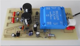
The illustrative picture: we have a 25-0-25Vac from secondary windings to the rectifiers (board). The fuse is rated 1.25A between mains and trafo's primary. Two 10nF caps to suppress noise when powering on, one cap in parallel with the power switch (at left) and the other (at right) in parallel with the primary windings.
Now, the 1.25A fuse "wasn't able" to protect the transformer from voltage surges of 250Vac (allowing also higher secondary voltages into the rectifiers/power caps). "Luckly", the transformer's thermal fuse did the job (probably costing the transformer itself by shorting its windings somewhere).
Before I test the transformer/amp with a dim bulb tester, I'd like to know how you do while DIYing or building you own power supplies.
Any schematics from you, regardless component values, would be VERY interesting to understand/learn how to have a strong, efficient, stable and fully protected Power Supply.
Can be both a reliable transformer section supply or/and the complete section, from power switch to the rectifiers, adding other protective components as well!
Many thanks in advance! 🙂
I'm doing some work now on an amp that had its transformer's thermal fuse burnt due to voltage surge and spikes of 250Vac while the amp must operate on our 230Vac mains.
So, while my dim bulb tester is not yet ready to see if there's a short in the transformer's primary, I was thinking of a very efficient, stable, steady and fully protected power supply to feed smoothly and continuosly a circuit without any or minimal troubles...
The illustrative picture: we have a 25-0-25Vac from secondary windings to the rectifiers (board). The fuse is rated 1.25A between mains and trafo's primary. Two 10nF caps to suppress noise when powering on, one cap in parallel with the power switch (at left) and the other (at right) in parallel with the primary windings.
An externally hosted image should be here but it was not working when we last tested it.
Now, the 1.25A fuse "wasn't able" to protect the transformer from voltage surges of 250Vac (allowing also higher secondary voltages into the rectifiers/power caps). "Luckly", the transformer's thermal fuse did the job (probably costing the transformer itself by shorting its windings somewhere).
Before I test the transformer/amp with a dim bulb tester, I'd like to know how you do while DIYing or building you own power supplies.
Any schematics from you, regardless component values, would be VERY interesting to understand/learn how to have a strong, efficient, stable and fully protected Power Supply.
Can be both a reliable transformer section supply or/and the complete section, from power switch to the rectifiers, adding other protective components as well!
Many thanks in advance! 🙂
the fuse is not really there to protect your transformer. It is there to prevent the circuits from catching fire in the event of failure. The fuse thus protects your house.
The thermal fuse is temperature operated, not current or voltage. It opens if the winding temperature goes over the rated fuse temperature. I think I see its lead wires on the second and third posts in the row of three at the bottom of your photo. If that fuse opens, your primary will not have continuity. You can check that by using an ohm meter between the white and yellow wires - the two posts on the upper row on the transformer. I don;t know what resistance to expect, but it will either be open or OK. It won't likely be "wrong." 200 ohms maybe?
On any working amp, if you unplug from the mains, turn the power switch to on, and measure resistance between the hot pins of the mains plug, you should see the resistance of the primary. If the primary is open, the bulb tester will not show anything.
Good design and "fully protecting" a power supply still has limits. Just as having seat belts and airbags in your automobile won;t let you drive into a tree at highway speeds and stay unharmed, you cannot makie a power supply safe from 100% of perils. You can fuse it really close to load current, but then you get nuisance fuse blows from small surges. And circuits on the secondary side can burn up but use less power than the mains fuse represents and thus not blow it. You can add anay secondary side fuses that are not already there, but the same caveat remains
Hi Enzo, thanks for the imput....
The thermal fuse is temperature operated, not current or voltage. It opens if the winding temperature goes over the rated fuse temperature. I think I see its lead wires on the second and third posts in the row of three at the bottom of your photo. If that fuse opens, your primary will not have continuity. You can check that by using an ohm meter between the white and yellow wires - the two posts on the upper row on the transformer. I don;t know what resistance to expect, but it will either be open or OK. It won't likely be "wrong." 200 ohms maybe?
...
Now, measuring this transformer from posts (bypassing the thermal post) we have 12.6 ohms, as you can see here:
An externally hosted image should be here but it was not working when we last tested it.
I took measurements with another amplifier (Kenwood KA-405) and DMM displayed 7.1 ohms. This amp is working perfectly.
The idea of this thread is to know how folks build up their PSU to their customized projects, sometimes highly specified projects. 🙂
Last edited:
If you want to have a great op amp and power amp dual power supply buy an HP 6255A DUAL DC POWER SUPPLY 0-40V, 0-1.5A. Even better buy one on eBay that needs repair. One just sold working for $21.50. The manual has schematics, PCB with component locations, theory of operation, how to test and calibrate with troubleshooting guide. You will learn a lot and have a great lab power supply. This power supply has current limit 0-1.5A, which means the amplifier under test can be protected when first powered up.
The problem with transformer and bridge power supplies is the current cannot be limited to a safe level, with big filter caps at moderate voltages it can generate up to 100 amp discharge pulses.
Link to down load free manual
http://www.home.agilent.com/agilent...6184&lc=eng&cc=US&nfr=-536902299.536879776.00
An externally hosted image should be here but it was not working when we last tested it.

Karl, I think your misunderstanding the thermal fuses operation in practice. Normal voltage spikes and surges won't cause the transformer to heat, there's far to much thermal inertia for that to happen.
As to PSU's I use when designing power amps and so on, well I have two (well three really). A small PCB with a 15-0-15 tranny on it. In some ways the most useful of all. And secondly two Farnell stabilised and adjustable 0-30 volts DC lab PSU's.
As to PSU's I use when designing power amps and so on, well I have two (well three really). A small PCB with a 15-0-15 tranny on it. In some ways the most useful of all. And secondly two Farnell stabilised and adjustable 0-30 volts DC lab PSU's.
Attachments
Ok, only for prolonged periods a 254V can heat it up, right?Karl, I think your misunderstanding the thermal fuses operation in practice. Normal voltage spikes and surges won't cause the transformer to heat, there's far to much thermal inertia for that to happen
...
Ok, only for prolonged periods a 254V can heat it up, right?
I'm not so sure it would tbh. Or not in practice should I say.
That's based on the transformer running at way below its rated capacity just powering the amp. You might be drawing 2 or 3 hundred milliamps at idle from a tranny rated at 2 or 3 amps. Even normal listening levels draw way below max ratings. So based on purely an increase in voltage from say 230 to 254, well I don't think that would cause excess core temperature rise tbh but transformer theory such as calculating these things isn't my field.
My instincts say... its not a problem 🙂 It will have failed "because they do" unfortunately, or, there is a real problem with the amp drawing excess current and its been left powered up in that state for enough time to heat the transformer (and such a fault would show immediately on test).
Reasonable overvoltage (say, no more than 20% or up to 276V 😱 for a 230V mains) will not burn the transformer itself.
Yes, they can blow a too tightly specified power amp or electrolytics and the resulting short damage the transformer, but a properly specified line fuse (say, 20/25% above expected max. "normal" consumption) should protect it.
As mentioned above, transformers have a lot of thermal mass, while a properly rated mains fuse should blow between 0.5 and 3 seconds (maximum) after shorting its secondary leads.
Now if your *thermal* fuse opened, the transformer must have been cooking a lot, for a lot of time (easily 15 minutes).
In over 10000 transformers delivered, I have seen less than a dozen burnt.
As an exception (justified in this case), I have now on my bench the power transformer from a 10 years old 300W 8 channel powered mixer where the fan shorted, and its dedicated winding cooked, without blowing the mains fuse.
I rewound it in full anyway, just to play it safe.
Now, if the main winding had shorted, the mains fuse would have blown in a second and the transformer would have suffered no damage..
I'm not so sure it would tbh. Or not in practice should I say.
That's based on the transformer running at way below its rated capacity just powering the amp. You might be drawing 2 or 3 hundred milliamps at idle from a tranny rated at 2 or 3 amps. Even normal listening levels draw way below max ratings. So based on purely an increase in voltage from say 230 to 254, well I don't think that would cause excess core temperature rise tbh but transformer theory such as calculating these things isn't my field.
My instincts say... its not a problem 🙂 It will have failed "because they do" unfortunately, or, there is a real problem with the amp drawing excess current and its been left powered up in that state for enough time to heat the transformer (and such a fault would show immediately on test).
Good news, my friends! 🙂
The transformer is fine!!! 🙂 (thermal fuse post apart!)
Under the dim bulb it was glow orange at any level. It delivers 28-0-28VAC with no variations, even after half an hour.
Idle adjustment was also done. The values were 18mV on both channels and I put them back to 11mV factory original specs.
An externally hosted image should be here but it was not working when we last tested it.
And now? 😀
Last edited:
Great news 🙂
Seems like its just "failed" as these things are prone to do. What next... that's up to you 😀 Just remember it has to be safe.
Seems like its just "failed" as these things are prone to do. What next... that's up to you 😀 Just remember it has to be safe.
Well, not sure if this can help in preventing anything, but I also put a 250V MOV across the primary...Great news 🙂
Seems like its just "failed" as these things are prone to do. What next... that's up to you 😀 Just remember it has to be safe.
So far so good...


You definitely must fit a 275 volt device for 230/240 volt mains. 250 is way to close for comfort... it could literally explode under normal high mains conditions.
An MOV won't prevent any normal failures from occurring but might give some benefit in cleaning up any transients on the mains. Lets say it does no harm generally.
An MOV won't prevent any normal failures from occurring but might give some benefit in cleaning up any transients on the mains. Lets say it does no harm generally.
It looks like those transients are stronger and happen far more often than we think.
Electrical Safety agencies around the World but specially in the EU monitored voltage feeding homes all over the place, and found that 3KV peaks are *very* common, hence the current *obligation* to Hi Pot test consumer products to 3 KV 😱
They are talking about raising it to 4KV
Electronics Weekly News | Test and Measurement | Understanding hi-pot testing and its standards
I don't how much saftety margin for Bmax you design your tansformers to but OEM from big companies here in the US regularly show heavy pri draw with +20% rated line V - up to 10x the open circuit magnetizing current draw - and thats the EI which are more resistant to saturation
I've had to double the pri fuse rating on products when tested at high line V for agency approval
I've had to double the pri fuse rating on products when tested at high line V for agency approval
Last edited:
You definitely must fit a 275 volt device for 230/240 volt mains. 250 is way to close for comfort... it could literally explode under normal high mains conditions.
...
Yeah, I just put it staying behind my thick plexiglas panel while testing the transformer without the thermal fuse (LOL!)
I know a 275V is way far safe for this purpose. Might put one soon.

Me too.I don't how much saftety margin for Bmax you design your tansformers to but OEM from big companies here in the US regularly show heavy pri draw with +20% rated line V - up to 10x the open circuit magnetizing current draw - and thats the EI which are more resistant to saturation
I've had to double the pri fuse rating on products when tested at high line V for agency approval
I had to raise all primary fuse ratings by 50% .
That said, I saw that the big increase is, as you noticed, at idle or low current conditions, but under high power demands it sort of "eats" or "swamps" the difference.
Maybe because the working point moves away from the very nonlinear "zero crossing" area, to give it a name.
As of B Max value chosen, beyond published spect I found that best is to use the best iron available and call it a day.
It ends out being the cheapest, considering all expenses.
I'm lucky my supplier imported a few Tons of very good Russian Si steel , the one that's bright (almost looks enamelled) with greenish-yellow streaks along the grain.
He has it in bulk and punches whatever's asked on demand.
Besides, his dies are very sharp and edges are perfect, material is very flat, a pleasure to work with.
Only scrapless EI lamination, of course; not much market here for anything fancy.
Toroids? ..... what's that? 😛
- Status
- Not open for further replies.
- Home
- Design & Build
- Parts
- An efficient, stable and fully protected Power Supply?