Intermittent DC Offset - Source or Amp?
Hello DIYers - I appreciate any and all help with my issue. Sorry, I am a newbie and it’s a long post...
I blew up a pair of speakers testing my "minimized" AudioSector LM3875 amp in the first few hours of its life and I am trying to figure out why. I checked and tested everything other than DC offset before hooking up my first pair of test speakers (8 ohm) and input source (a Microsoft Zune MP3 player working off battery only). I cycled the power at least 20 times before hearing the loud hum from the power supply and a crackle and hum in the speakers that resulted in blown speakers.
I posted my question on the commercial-gainclone-kit thread here:
http://www.diyaudio.com/forums/audi...it-building-instructions-165.html#post3483962
After reading info AndrewT replied with, I put the power supply in a box with good grounds, including a ground-break circuit and tested everything again. This time I also tested DC offset as explained in the commercial-gainclone-kit thread. DC offset as measured was 47/69. Once again the amp didn't send anything other than sweet sounds to the speakers through many on-off cycles before the horrible hum shot through attempting to foil my listening efforts for a second time. This time I had 4 ohm single driver car speakers hooked up and they survived the hum.
Could this problem have been caused by DC at the input from my Microsoft Zune MP3 player that was amplified and sent to the speakers? I have not used the Zune since the second time this has happened. I instead tried an NAD 1600 Tuner-Preamp and Denon CD player and they seem to be a good match for this amp. Nothing but sweet sounds so far, but I want to make sure I understand what happened to blow up my speakers before getting too comfortable with this amp.
Here's what I built:
The AudioSector board layout is here:
http://www.audiosector.com/images/lm3875_se_pcb.gif
I followed the instructions here:
http://www.diyaudio.com/forums/audi...cial-gainclone-kit-building-instructions.html
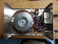
My power supply uses a 330va toroid with two 25v secondary windings into one rectifier board. I didn't have C1 and C2 installed when the first speakers blew, but I did have C1 and C2 installed the second time the hum shot through almost blowing up a second pair.
On the amp boards, I have R1 installed with the supplied 200 ohm resistor. In post #3, Peter Daniel mentions installing a small 4.7uF electrolytic cap in place of R1 to "protect the amp from DC that may be produced by a source component".
I did not install Rz or Cz as these components are not included in the kit. I understand these values should be Rz 2.7R and Cz 0.1uF if I choose to install them. I did a little reading about Zobel networks and it seems installing this won’t impact the sound and could also save my speakers.
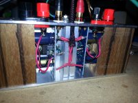
I built a star ground on the amp boards using 14ga copper wire between the output grounds (OG) on each main board. I have power going through an umbilical to the power supply rectifier board. I tied PG+ and PG- together with a 14ga copper wire and used one wire in the umbilical from the rectifier ground to the star ground point in the amp. I have another ground wire in the amp going from the star ground point to the amp chassis.
So what do you think? Could it be the source injecting DC at the inputs, or is there some intermittent issue with my amp build that is waiting to destroy another pair of speakers?
Thanks for reading! -Glen
Hello DIYers - I appreciate any and all help with my issue. Sorry, I am a newbie and it’s a long post...
I blew up a pair of speakers testing my "minimized" AudioSector LM3875 amp in the first few hours of its life and I am trying to figure out why. I checked and tested everything other than DC offset before hooking up my first pair of test speakers (8 ohm) and input source (a Microsoft Zune MP3 player working off battery only). I cycled the power at least 20 times before hearing the loud hum from the power supply and a crackle and hum in the speakers that resulted in blown speakers.
I posted my question on the commercial-gainclone-kit thread here:
http://www.diyaudio.com/forums/audi...it-building-instructions-165.html#post3483962
After reading info AndrewT replied with, I put the power supply in a box with good grounds, including a ground-break circuit and tested everything again. This time I also tested DC offset as explained in the commercial-gainclone-kit thread. DC offset as measured was 47/69. Once again the amp didn't send anything other than sweet sounds to the speakers through many on-off cycles before the horrible hum shot through attempting to foil my listening efforts for a second time. This time I had 4 ohm single driver car speakers hooked up and they survived the hum.
Could this problem have been caused by DC at the input from my Microsoft Zune MP3 player that was amplified and sent to the speakers? I have not used the Zune since the second time this has happened. I instead tried an NAD 1600 Tuner-Preamp and Denon CD player and they seem to be a good match for this amp. Nothing but sweet sounds so far, but I want to make sure I understand what happened to blow up my speakers before getting too comfortable with this amp.
Here's what I built:
The AudioSector board layout is here:
http://www.audiosector.com/images/lm3875_se_pcb.gif
I followed the instructions here:
http://www.diyaudio.com/forums/audi...cial-gainclone-kit-building-instructions.html
My power supply uses a 330va toroid with two 25v secondary windings into one rectifier board. I didn't have C1 and C2 installed when the first speakers blew, but I did have C1 and C2 installed the second time the hum shot through almost blowing up a second pair.
On the amp boards, I have R1 installed with the supplied 200 ohm resistor. In post #3, Peter Daniel mentions installing a small 4.7uF electrolytic cap in place of R1 to "protect the amp from DC that may be produced by a source component".
I did not install Rz or Cz as these components are not included in the kit. I understand these values should be Rz 2.7R and Cz 0.1uF if I choose to install them. I did a little reading about Zobel networks and it seems installing this won’t impact the sound and could also save my speakers.
I built a star ground on the amp boards using 14ga copper wire between the output grounds (OG) on each main board. I have power going through an umbilical to the power supply rectifier board. I tied PG+ and PG- together with a 14ga copper wire and used one wire in the umbilical from the rectifier ground to the star ground point in the amp. I have another ground wire in the amp going from the star ground point to the amp chassis.
So what do you think? Could it be the source injecting DC at the inputs, or is there some intermittent issue with my amp build that is waiting to destroy another pair of speakers?
Thanks for reading! -Glen
Attachments
Last edited:
Have you wired the MAG to Chassis bridge rectifier correctly?
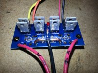
Have you kept the dual secondaries separate to feed the 8 rectifier diodes?
Are you using a 3pole power output socket, with +ve, Zero Volts and -ve?
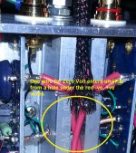
Can I see a third wire entering the bolted PE connection?
Have you kept the dual secondaries separate to feed the 8 rectifier diodes?
Are you using a 3pole power output socket, with +ve, Zero Volts and -ve?
Can I see a third wire entering the bolted PE connection?
Insert a temporary DC block between your Source and your Power Amplifier (both channels)
A 1uF would do to start with, 10uF would allow for low Zin of the Power Amplifier.
A 1uF would do to start with, 10uF would allow for low Zin of the Power Amplifier.
Hi AndrewT,
Thanks for taking some time to comment! Sorry, but I am not familiar with some of the acronyms, but here are my answers...
Have you wired the MAG to Chassis bridge rectifier correctly?
*The Chassis bridge rectifier is wired correctly. Sorry, what does "MAG" mean?
Have you kept the dual secondaries separate to feed the 8 rectifier diodes?
*Yes. Two wires from each secondary go to the rectifier.
Are you using a 3pole power output socket, with +ve, Zero Volts and -ve?
*Are you referring to the XLR socket? That is a 5 pin. I am using one pin for +ve, one pin for -ve, one pin for Zero Volts, and the ground lug to connect the amp chassis to the physical ground lug on the power supply chassis. This assures that the ground between the amp chassis and power supply touches first. If you're asking about the power plug to mains power, yes, that has 3 pins.
Can I see a third wire entering the bolted PE connection?
*Sorry, not sure what you mean by "PE"?
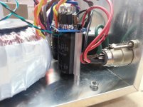
PE = Protective Earth. That big bolted connection with the two green wires that are far too long.
MAG = Main Audio Ground. More often referred to as Star Ground.
I see yellow connections as well as green and yellow wires from adjacent terminals.
MAG = Main Audio Ground. More often referred to as Star Ground.
I see yellow connections as well as green and yellow wires from adjacent terminals.
Insert a temporary DC block between your Source and your Power Amplifier (both channels)
A 1uF would do to start with, 10uF would allow for low Zin of the Power Amplifier.
Thanks again AndrewT! Question: Should this be an electrolytic cap? Also, since the problem is intermittent, how will I know that this has done anything?
BTW, I have to scrounge up some caps, so this will take a while. 🙂
electro will block.
Keep it in circuit for an extended test period.
If you can get a DC detect circuit to monitor the output with a big flashing LED or a Klaxon to tell you the DC is coming from before or after the blocker.
Keep it in circuit for an extended test period.
If you can get a DC detect circuit to monitor the output with a big flashing LED or a Klaxon to tell you the DC is coming from before or after the blocker.
PE = Protective Earth. That big bolted connection with the two green wires that are far too long.
MAG = Main Audio Ground. More often referred to as Star Ground.
I see yellow connections as well as green and yellow wires from adjacent terminals.
I followed this article below and an article on Decibel Dungeon to build the ground circuit. I don't have any audible issues with the grounding, what is the effect of those wires being too long? They are currently about a couple of cm in length. The green wires go from the mains earth to the chassis ground lug, and the ground on the xlr connector to the ground lug.
Earthing (Grounding) Your Hi-Fi - Tricks and Techniques
For MAG, I have one black wire going from the star ground in the amp to the PG point on the rectifier. That yellow wire goes from the PG point on the rectifier to the ground break circuit, as in the documentation I followed. From there it goes to the chassis ground lug.
Attachments
electro will block.
Keep it in circuit for an extended test period.
If you can get a DC detect circuit to monitor the output with a big flashing LED or a Klaxon to tell you the DC is coming from before or after the blocker.
Okay, thanks...
So far you have only been concerned with grounding and input. Any comment on Rz, Cz? Should I add that Zobel?
Update
Well, no update really other than to say I haven't changed the amp. It is working too well right now!
I built a pair of 72" high PVC Transmission Line speakers using Dayton Audio RS100-8 4" full range drivers and it all sounds really good together. I am still messing a bit with the baffle step correction on the speakers and I plan to add super tweeters soon.
I got a couple of replies to the pictures I posted on the chip amp picture forum suggesting I add bigger caps to the PSU. So I am going to try some caps offered to me to see if I like the sound.
So at this point, I don't have a problem with this amp. I think what happened was DC amplified from my Zune. Nothing but sweet sound with the NAD 1600 preamp hooked up, so that's what I'm going to use with this amp. Thanks again for the help on this forum.
Did you try big caps for power supply?...it will make a big difference 😉
The Big Caps
Yup, the big caps are in. Another DIYer generously sent me a pair of Rubycon 4700uF caps which I installed today. They were a tight fit but after changing a couple of things in my PSU they look right at home.
As far as the sound, yes there is an improvement. And it's a fairly large one! The amp sounds better with the larger filter caps than it did without them. I will characterize the lower octaves as tighter and with more punch. Vocals sound more rounded and drums are more detailed. Violins more full... The sound is in general more pleasing.
In short I like the sound and will keep going this direction to find out if I hear improvements with 6800uF caps, then 10000uF caps, etc.
Thanks for your continued interested and great advice!!
Attachments
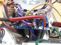
Looks good! I'm glad that you like the improvement. After adding bigger PSU caps to my Audiosector Chipamp I find myself in disbelief that he supplies such small caps with the kit.
But it's an easy change to do and sounds great, maybe Peter isjust encouraging us to try for ourselves!
Will more capacitance make for more improvement? Maybe... The biggest change (from 10uF to 4700uF per rail) has already happened.
But it's an easy change to do and sounds great, maybe Peter isjust encouraging us to try for ourselves!
Will more capacitance make for more improvement? Maybe... The biggest change (from 10uF to 4700uF per rail) has already happened.
I'm using 15,000uF Panasonic TS-HA caps on that same PSU board, mounted similar to what you have.
Looks good! I'm glad that you like the improvement. After adding bigger PSU caps to my Audiosector Chipamp I find myself in disbelief that he supplies such small caps with the kit.
Thanks for the assist! I would have bought them up front from Peter if they were offered as an option.
But it's an easy change to do and sounds great, maybe Peter isjust encouraging us to try for ourselves!
And after all, isn't that why we're here! 🙂 I'm having a blast with my DIY projects.
Will more capacitance make for more improvement? Maybe... The biggest change (from 10uF to 4700uF per rail) has already happened.
That makes a lot of sense. I will point to point #2 above, however! LOL... Since I only used one of the rectifier kits with this amp, I was thinking of building up the other in a snubberized version with larger filter caps. It will be interesting to directly compare the two PSUs.
I'm using 15,000uF Panasonic TS-HA caps on that same PSU board, mounted similar to what you have.
How do they sound? Have you compared them to 4700uF caps?
I made a comparison to 2,200uF Panasonic FC caps, and I chose the 15mF ones over them. Mind you this was with the LM4780 bridged amp that I had before, but now that I'm running an LM3886 amp I'm still using the same PSU board setup.
http://www.diyaudio.com/forums/chip...l-rules-custom-bridged-story.html#post1625608
One thing to note if you read on in that thread, is that I have since removed the series resistor+capacitor pair (R3+C5 and R4+C6) from each rail, they were the cause of really bad hum when connected to my PC.
http://www.diyaudio.com/forums/chip...l-rules-custom-bridged-story.html#post1625608
One thing to note if you read on in that thread, is that I have since removed the series resistor+capacitor pair (R3+C5 and R4+C6) from each rail, they were the cause of really bad hum when connected to my PC.
Last edited:
I made a comparison to 2,200uF Panasonic FC caps, and I chose the 15mF ones over them. Mind you this was with the LM4780 bridged amp that I had before, but now that I'm running an LM3886 amp I'm still using the same PSU board setup.
http://www.diyaudio.com/forums/chip...l-rules-custom-bridged-story.html#post1625608
One thing to note if you read on in that thread, is that I have since removed the series resistor+capacitor pair (R3+C5 and R4+C6) from each rail, they were the cause of really bad hum when connected to my PC.
Nice build! I wonder why the zobel network would have caused hum? Also, what did you use to make your measurements? I have been using my ear to tune my DIY projects and would like something a little more empirical to base my own findings on.
Well, no update really other than to say I haven't changed the amp. It is working too well right now!
...
So at this point, I don't have a problem with this amp. I think what happened was DC amplified from my Zune. Nothing but sweet sound with the NAD 1600 preamp hooked up, so that's what I'm going to use with this amp. Thanks again for the help on this forum.
Ok, just so you know we haven't really addressed your problem ...
The minimal gainclone has no input coupling cap (blocks DC) and no feedback cap (blocks gain of DC)
Have you added Andrew's suggestion of an input coupling cap ~10uF? Do you have a schematic for the Zune (does it have a coupling cap?)? The NAD will probably have output coupling caps (22uF electros 😱 )
So if it sounds good with the NAD, don't be afraid of electros and proper technical input coupling! 😉
Always turn the gainclone off first, then wait 10 seconds (so it'll fully discharge), then everything else. Reverse for turn on.
If you're gonna live dangerously, do it with info:
http://www.diyaudio.com/forums/chip-amps/184256-lm1875-vs-lm3886-4.html#post3505206
😉
Last edited:
Ok, just so you know we haven't really addressed your problem ...
The minimal gainclone has no input coupling cap (blocks DC) and no feedback cap (blocks gain of DC)
Yes, I understand... Where does the feedback cap go?
Have you added Andrew's suggestion of an input coupling cap ~10uF? Do you have a schematic for the Zune (does it have a coupling cap?)? The NAD will probably have output coupling caps (22uF electros 😱 )
So if it sounds good with the NAD, don't be afraid of electros and proper technical input coupling! 😉
Not yet, but I have the part and I plan to - soon... No schematic for the Zune... What is the significance the coupling cap in the NAD possibly being 22uF? Just wondering why 22, why not 10 or 1...
Always turn the gainclone off first, then wait 10 seconds (so it'll fully discharge), then everything else. Reverse for turn on.
That's good advice for any system of separates. I have 3 amps in my main system and have the wife trained on that order of operation! 🙂
If you're gonna live dangerously, do it with info:
http://www.diyaudio.com/forums/chip-amps/184256-lm1875-vs-lm3886-4.html#post3505206
😉
...Ouch! I run all my equipment on UPSes with power conditioning hoping to somewhat immunize my stuff from fluctuating power at the mains.
- Status
- Not open for further replies.
- Home
- Amplifiers
- Chip Amps
- Intermittent DC Offset? Source or Amp?