If you have only 1 transformer and are building a guitar amp, please post on the instrument "board".
If you have a pair of O/P trafos to build a music reproduction amp, you can use the 6.6 KOhm primary "iron" usually used with 6L6s in combination with a PP EL84 pair. Set up for plenty of GNFB, L_RD knows, you have lots of magnetic headroom and need to compensate for a somewhat low load impedance. 8 KOhm primary "iron" is the norm for PP EL84s.
If you have a pair of O/P trafos to build a music reproduction amp, you can use the 6.6 KOhm primary "iron" usually used with 6L6s in combination with a PP EL84 pair. Set up for plenty of GNFB, L_RD knows, you have lots of magnetic headroom and need to compensate for a somewhat low load impedance. 8 KOhm primary "iron" is the norm for PP EL84s.
If you have only 1 transformer and are building a guitar amp, please post on the instrument "board".
If you have a pair of O/P trafos to build a music reproduction amp, you can use the 6.6 KOhm primary "iron" usually used with 6L6s in combination with a PP EL84 pair. Set up for plenty of GNFB, L_RD knows, you have lots of magnetic headroom and need to compensate for a somewhat low load impedance. 8 KOhm primary "iron" is the norm for PP EL84s.
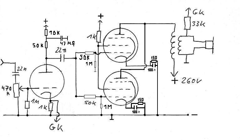
And If I try use two EL84s on parallel to get 4K? I already I've seen this before, like this:
You can't use a PP O/P trafo in a PSE setup.
I'm still trying get it work, but sounds very poor until now, with low amplidute and some distortion too.
I already tried setup a nfb but dont solved the problem. Now I tried with a EL86 tube and sound almost like the EL84.
I really need a help here. All that I'm want is a simple single ended amplifier, but unfortunately I just have now this PP transformer to 6L6...

Hm, but this OT is 8k. The 6l6 I think that is 6.6K or less, right?
This LM317 help with the cathode bias, and if I right, are you suggesting that my problem could be fixed with this?
The bias will keep the el84's inside their safe operating area.
Or you could replace the el84 with el34, double the bias current and get twice as much power.
But will work with my 6l6 pp transformer?
A mismatched transformer gives worse distorsion figures but it works.
That's precisely why I suggested GNFB, earlier.
The uploaded self splitting circuit can't obtain the full power capability of a PP EL84 pair.
 AAMOF, that design is good for approx. 4 WPC. The CCS in the cathode circuitry forces Class "A" operation. Also, the ultralinear mode leads to inadequate damping factor. Sorry, thats not a good design.
Take a look at "El Cheapo". Using EL84s instead of 'AQ5s requires changes in the RC bias network, but that's it, for the O/P stage. Use 68 nF. caps. at the I/Ps and 150 Kohm grid to ground resistors. The 6L6 O/P "iron" has "tons" of magnetic headroom, for this application. Go for full bass extension. EL84s are somewhat easier to drive than 'AQ5s (a member of the 6V6 family). Take advantage of that fact and increase the % of the net O/P voltage fed back, slighty. Use meter matched 9.1 KOhm carbon composition parts, instead of the 10 KOhm parts shown.
That's precisely why I suggested GNFB, earlier.
The uploaded self splitting circuit can't obtain the full power capability of a PP EL84 pair.
.
I have built the SIPP circuit and it sounds very good.
The CCS ensures 80mA of current is used and so it gives a good output level.
I have built the SIPP circuit and it sounds very good.
The CCS ensures 80mA of current is used and so it gives a good output level.
A self splitting O/P stage starts out at 1/2 power and goes downhill, from there. It's the same situation as a twin triode differential gain block, with only 1 grid driven. 1/2 μ is the theoretical max. gain and you never get that much.
Money on both parts and electricity is being thrown away.
Reason enough to "black ball" the setup.Money on both parts and electricity is being thrown away.
Its worth the 80ma to get a great sound.
It puts my class AB and class D amps to shame.
I now only listen to the SRPP/SIPP valve amplifier.
It's not Class "A" that's an issue. Class "A" triodes are about 20% efficient. A Class "A" self splitting triode setup is 10% efficient.  UL mode, as shown in the schematic, is more efficient than triode, but the 50% reduction in net efficiency, due to self splitting, holds true.
You can get the same great sound, along with 2X the power and 2X the efficiency by installing a phase splitter. It's not especially difficult to be technically correct and good sounding too.
UL mode, as shown in the schematic, is more efficient than triode, but the 50% reduction in net efficiency, due to self splitting, holds true.You can get the same great sound, along with 2X the power and 2X the efficiency by installing a phase splitter. It's not especially difficult to be technically correct and good sounding too.
But will work with my 6l6 pp transformer?
Have you measured your turns ratio?
Instead of guessing measure it.
1. Feed a test tone into your amp.
2. Measure the plate voltage on one tube.
3. measure the output voltage
4. calculate turns ratio = Plate voltage * 2 / V out
5. calculate impedance ratio :
Turns ratio ^ 2 * Zout = Plate - Plate impedance
For instance if you are using an 8 ohm tap and you drive it to 1Vrms out and measure 28Vrms at the plate then:
28^2 * 8 = 6272 ohms plate to plate
Why guess when you can easily measure it?
It's not Class "A" that's an issue. Class "A" triodes are about 20% efficient. A Class "A" self splitting triode setup is 10% efficient.
You can get the same great sound, along with 2X the power and 2X the efficiency by installing a phase splitter. It's not especially difficult to be technically correct and good sounding too.
My next project is a class AB output stage with a pre-amp on the front driving a phase splitter.
Will be interesting to see how it sounds compared to the SIPP model.
- Status
- This old topic is closed. If you want to reopen this topic, contact a moderator using the "Report Post" button.
- Home
- Amplifiers
- Tubes / Valves
- 6L6 transformer on EL84