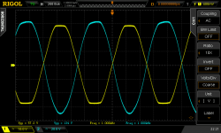
Trying to drive 4 KT88's connected to a Hammond 1650T to the max (120 Wrms rated), I saw this on my oscilloscoop. The 12AT7 LTP phase splitter has signal swing to spare (blue line), but the 4 ohm transformer tap shows the clipping yellow line, connected to a 4 ohm resistive load. Is this the saturation effect? Or is something else going on.


Last edited:
It's 420 volts. The reason I think it's saturation, is because the Vpp is around 120W into 4 ohm. Would be too much of a coincidence. And a clipping LTP looks dufferent AFAIK. But I'm not shure.What is your B+ voltage?
The positive peak of the driver signal is flattening a bit. My guess is that you hit grid current on the output valves there. With mosfet source followers you could probably go into AB2 and get some more watts if you want.
At such frequency (1Khz) the OPT CANNOT saturate !
It would be different below, say, 50 or 30 Hz.
As said above, tubes are probably running out of current or voltage.
I'm curious to see what happen in slghtly changing the load, f.e. from 3 to 5 Ohms.
Yves.
It would be different below, say, 50 or 30 Hz.
As said above, tubes are probably running out of current or voltage.
I'm curious to see what happen in slghtly changing the load, f.e. from 3 to 5 Ohms.
Yves.
Flux density decreases as frequency increases. At 1000Hz, I wouldn't expect that to occur, at least not unless you hit insane volts/turns ratios somehow. Besides, saturation looks more like square waves.
It also looks like your driver doesn't have enough drive capability. The positive peaks are flattening, and that's what grid current looks like when you have inadequate current sourcing. You've taken the Vgk of the finals as far as you can go. Any farther, and you're in Class AB2.
It also looks like your driver doesn't have enough drive capability. The positive peaks are flattening, and that's what grid current looks like when you have inadequate current sourcing. You've taken the Vgk of the finals as far as you can go. Any farther, and you're in Class AB2.
Yes, the LTP is flattening a bit on one peak but that is not the cause of the output clipping. However, any more signal and the LTP would be the limit even if the output stage could cope.
For maximum possible output you want one side of the output to be hitting a voltage limit (bottoming) while the other side is at the current limit (cut-off) - they swap over at the opposite peak. This requires the right bias and right impedance load. For smoother clipping you want to avoid this, but at the expense of slightly less power.
For maximum possible output you want one side of the output to be hitting a voltage limit (bottoming) while the other side is at the current limit (cut-off) - they swap over at the opposite peak. This requires the right bias and right impedance load. For smoother clipping you want to avoid this, but at the expense of slightly less power.
But could it really be the output tubes/stage?? I mean, it's 420V into 4 KT88's with a 1900 ohm output transformer. Although the OPT is rated at 120Wrms, the KT88's should be capable of putting out way more than 120W!
Tonight, I'll replace the 12AT7 with an ECC99 I've got lying around. It's able to source more current than the AT7.
Tonight, I'll replace the 12AT7 with an ECC99 I've got lying around. It's able to source more current than the AT7.
Out of curiosity, aren't the power tubes supposed to amplify the signal? I mean, looking at the waveforms, I get that the light blue signal is the output of the pentodes, and the yellow one should be the input to them. In that manner, the previous stage is clipping and we have grid current for the pentodes.
What am I missing? 🙁
What am I missing? 🙁
Last edited:
To know what each KT88 is doing, add a 1 or 10 ohm resistor in series ( don't know your setup ) with the cathode and measure across it with your scope while the output is clipping. I agree with DF96 comments.
Last edited:
How much does your B+ sag from 420v when you start to see the clipping? What are the specs of your power transformer?
the KT88's should be capable of putting out way more than 120W!
They should but looks like they cannot. Some distortion is coming from the 12AT7 however you output stage is clipping. Nothing to do with the transformer saturation. More likely operative conditions for your KT88's are not enough for more than 50W per pair in class AB1. Maybe the specs of your actual KT88's are not exactly the same as the average datasheet KT88. I would
try to reduce the anode current a little bit (more negative bias) and see....
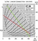
It's set up as class AB1. Loadlines added below.Bias? Class A or B? Show us your load line.
Correct, but a clipping long-tailed-pair lookes very different AFAIK!Out of curiosity, aren't the power tubes supposed to amplify the signal? I mean, looking at the waveforms, I get that the light blue signal is the output of the pentodes, and the yellow one should be the input to them. In that manner, the previous stage is clipping and we have grid current for the pentodes.
What am I missing? 🙁
It's a MOSFET series regulated PSU. The voltage stays constant while this clipping occurs.How much does your B+ sag from 420v when you start to see the clipping? What are the specs of your power transformer?
I'll try and see what happens!I would
try to reduce the anode current a little bit (more negative bias) and see....

Correct, but a clipping long-tailed-pair lookes very different AFAIK!
Well, that is another story! 😛 Oh man, for a minute I thought I was going crazy.
Have we ruled out the preamp?
Well, that is another story! 😛 Oh man, for a minute I thought I was going crazy.
Have we ruled out the preamp?
Yes, it's a fluke function generator with (near) perfect sine output and signal swing to spare, but as suggested above, it's probably not the PI, but the output stage where things go wrong.
The load line shows you will get at most a 350V (x2) swing on each anode. To get more you need AB2. My arithmetic says that this will give you 129W max, so you are quite close to the limit. In valve-land a 10-20% discrepancy from calculated values is regarded as 'spot-on'!
A bit less quiescent current may help, but you will then need more grid swing.
A bit less quiescent current may help, but you will then need more grid swing.
So it's actually working exactly as it should? Let me see if I get this right (learning curve, etc.). I'm just witnessing the ouput valves going into clipping. The gridcurrent that 'tries' to flow because of this clips the tops of the signal comming from the PI, because it's not suited to sink this current. If I used e.g. cathode followers after the main PI, I could get it into AB2, and get some more out of them (which I'm not trying to do btw, since the OPT is rated 120Wrms). Lowering the bias would give the output tubes a bit more signal swing, thus a bit more power into the load. Another option would offcourse be to increase the HT. Does that sound about right??The load line shows you will get at most a 350V (x2) swing on each anode. To get more you need AB2. My arithmetic says that this will give you 129W max, so you are quite close to the limit. In valve-land a 10-20% discrepancy from calculated values is regarded as 'spot-on'!
A bit less quiescent current may help, but you will then need more grid swing.
Last edited:
- Status
- Not open for further replies.
- Home
- Amplifiers
- Tubes / Valves
- Is this transformer saturation? (pictures inside)