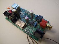
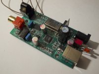
Attached are pictures of my USB converter board. I am using the I2S output as you can see from the soldered wires. Since the pictures I have connected the 5V regulator directly to 14V on the CD player PCB that I am using for its DAC and output stages. I have also removed the 12.000MHz clock and now run the clock on a separate low noise clock board. Both modifications resulted in significant improvements.
What else can I do to this board?
I was thinking that with the clock on a different board, I don't need 5V on the USB board anymore. Can I bypass the 5V regulator and hook the 14V directly to the 3.3V surface mount regulator that powers the TE7022?
Is there a quality 3.3V surface mount regulator that can be recommended as an upgrade to the original one?
Any other suggestions for improvement?
Attachments
Hello
Where did you buy the Tenor TE7022 USB converter board ?
Thank
Bye
Gaetan
I got it off ebay:
http://www.ebay.ca/itm/200723844485?ssPageName=STRK:MEWNX:IT&_trksid=p3984.m1439.l2649
Those wires with no ground reference will not do the signals any good!
From the pictures you'll notice that there is a ground next to SCLK and I have connected it to the PCB of the DAC and output stage.
Not close enough, twisted pairs would be better, keeping the signals return path in intimate proximity. Those connectors and pin outs don't help, sig-gnd-sig-gnd-sig-gnd would be much better allowing for either twisted pair for each signal or small co-ax cables.
Not close enough, twisted pairs would be better, keeping the signals return path in intimate proximity. Those connectors and pin outs don't help, sig-gnd-sig-gnd-sig-gnd would be much better allowing for either twisted pair for each signal or small co-ax cables.
Oh, I see. But then why not use coax or twisted pairs with this board and connect all the grounds to GND?
It creates a discontinuity for the return signal. The following, while related to PCBs stands for the signal going down a cable, hence all high speed digital interfaces are LVDS these days.
http://www.x2y.com/filters/TechDay0...log_Designs_Demand_GoodPCBLayouts _JohnWu.pdf
The pigtail acts like a slot in the ground plane.
A more humorous look at some of the problems by one of the real experts in these sorts of problems, his web site is worth a look, lots on Audio grounding problems, for the signal integrity side of things Dr Howard Johnson is a good source.
The 10 Best Ways to Maximize Emission from Your Product
Signal Consulting, Inc. - Dr. Howard Johnson
It creates a discontinuity for the return signal. The following, while related to PCBs stands for the signal going down a cable, hence all high speed digital interfaces are LVDS these days.
http://www.x2y.com/filters/TechDay0...log_Designs_Demand_GoodPCBLayouts _JohnWu.pdf
The pigtail acts like a slot in the ground plane.
A more humorous look at some of the problems by one of the real experts in these sorts of problems, his web site is worth a look, lots on Audio grounding problems, for the signal integrity side of things Dr Howard Johnson is a good source.
The 10 Best Ways to Maximize Emission from Your Product
Signal Consulting, Inc. - Dr. Howard Johnson
All very interesting and informative. However, I was asking for advice on tweaking this board that is already made and that I am already using. If I understand correctly, you are not happy with using either coax or twisted pairs whose grounds are connected together to the corresponding PCB ground at each end. Do you then have any other practical solution for the signal grounding issue that you have identified?
No coax or twisted pairs are the best way to distribute the signals from one board to another. It is always better though if the ground for each signal is next to the signal. The grounds have to be connected at each end, what I am saying is that it is not optimal to have the ground pigtailed to a ground point some way from the positive element of the signal. All digital signals are best thought of as a differential pair consisting of the signal and its return path, both should be equal and in very close proximity to avoid any impedance mismatches.
OK, that was my misunderstanding. I do appreciate your help and wiring is now added on the to-do list for this little project...
change the 5V supply
Hi,
I've got expirience with DIYParadise's Monica for a long time now.
It onced used a PCM2706 USB chip supplied by USB 5V.
The far most impressive tweak I had was to play with a very clean 5V source 🙂
I started to cut the USB power supply and used mignon batteries, then expensiv tinfoil lead batteries which had "around" 5V volts.
The difference was huge. Why ? ->The battery is isolated from any GND issue you mave have with mains, also the lack of very high frequency trash. The difference is huge: Jitter improved (to my ears), it was much more quiete. And so staging, dynamics, details...improved
Now I use a 12V7Ah standard Lead acid /gel battery with a Paul Hynes 5V series regulator and this was again a small step further.
BTW: Different batteries changed the sound in my tests. Also capacitor after the battery did, I only enjoyed the "Black Gates"...but didn't had a lot of other things laying around, at least standard caps didn't sound well.
Bringing it to point: My expirience was that the supply modification of the USB chip was a huge step. I guess it can be easily done too at your PCB. Just remove the Plus of the USB and connect the battery pack to + and the GND. (USB GND is still needed)😀
Good Luck
Bringing it to point: My expirience was that the supply modification of the USB chip was a huge step. I guess it can be easily done too at your PCB. Just remove the Plus of the USB and connect the battery pack to + and the GND. (USB GND is still needed)😀
Good Luck
McLanz, this is interesting to me. The board came with a switch for using an external power source. I bypassed the switch (making sure to switch the USB power off) and bypassed the little surface mount rectifier and connected 14V from the CD player PCB directly to the 5V regulator. Do you think the battery would be even better? Can you send me a link to a typical battery for this type of application?
Hello
Anybody did try the TE7022 USB converter on a old Mac computer with a
OS 9, does it work good with a Mac and OS 9 ?
Thank
Bye
Gaetan
Anybody did try the TE7022 USB converter on a old Mac computer with a
OS 9, does it work good with a Mac and OS 9 ?
Thank
Bye
Gaetan
Last edited:
Anybody did try the TE7022 USB converter on a old Mac computer with a
OS 9, does it work good with a Mac and OS 9 ?
I don't know the answer to that question, but the table partway down the page on the following link suggests that it should work, since it is a USB Audio Class 1.0 device:
Ratoc Systems: Digital Audio Transport with USB Audio Class 2 Support RAL-24192UT1:
Hi, yes I do so! I'm pretty sure you'll like it!😎
Well the battery "to start" is maybe laying around already its not neccearry needed to have a special quality for a first test.
A) to just replace the 14V CDP supply take a Panasonic sealed lead acid - gel battery like this: "LC-R127R2PG"
thats what I did with success!
or
use what is more practival use a smaller one with 12Volts but less capacity maybe 3.2Ah. Its smaller 🙄 of course you need a charger then but thats cheap.
B)
To supply 5V you may order very good regulator or use batteries in the range of 5V volts some tolerance is allowed like +/- 1V (read the datasheet!!!).
I would advise to buy the Panasonic battery and start this way. Such a battery is always good to have around
Jochen
I would advise to buy the Panasonic battery and start this way. Such a battery is always good to have around
Jochen
If I got such a battery would I need to have a charger hooked up to it?
Good - lets start
Hi good you have already a battery!
No you don't need a charger all the time - this would even take away the positive effect of the battery. Don't contact the battery all the the time just for the hours it get charged.
I don't think your USB chip will consume a lot of energy! It will be just a few mA's. So charge your battery initially - and then hook it to your USB chip. It should last two weeks or longer without problems...
The 12V battery should be charged again when entering 12,3V. This avoids degradation.
Today just measure the voltage and if above that just hook it to your chip 😀
and have some good music
PS: If you're going to take away the battery often...mark the poles with colour or solder in a diode to avoid killing your USB chip by a second of not being concentrated
Jochen
If I got such a battery would I need to have a charger hooked up to it?
Hi good you have already a battery!
No you don't need a charger all the time - this would even take away the positive effect of the battery. Don't contact the battery all the the time just for the hours it get charged.
I don't think your USB chip will consume a lot of energy! It will be just a few mA's. So charge your battery initially - and then hook it to your USB chip. It should last two weeks or longer without problems...
The 12V battery should be charged again when entering 12,3V. This avoids degradation.
Today just measure the voltage and if above that just hook it to your chip 😀
and have some good music
PS: If you're going to take away the battery often...mark the poles with colour or solder in a diode to avoid killing your USB chip by a second of not being concentrated
Jochen
A regulator after a bettery is a very good idea, as digital likes nice solid supplies, and for digital it is the best option. There is also a good thread on battery noise.
Hi good you have already a battery!
Unfortunately I don't have a battery yet. I was wondering if I would need to buy a charger too. What kind of charger would work for that battery?
- Status
- Not open for further replies.
- Home
- Source & Line
- PC Based
- Tweaking a cheap Tenor TE7022 USB converter board