I would not trust the calculations on that site. He doesn't seem to have understood how SRPP actually works.
For some understanding try Merlin Blencowe's site - the valve wizard.
For some understanding try Merlin Blencowe's site - the valve wizard.
The original designer?
To calculate the output impedance you need to know the valve operating point so you can find the mu and ra. Then plug these into the formula which Merlin gives on his site.
Then remember that output impedance and optimum load impedance are not the same thing so be clear what you actually want to know.
LTSpice sim: about 400R (at 1kHz)
Thank you, Thomas link: platten spieler calculator sim about 321 ohms, can be good for 300 ohms load?
Thank you, Thomas link: platten spieler calculator sim about 321 ohms, can be good for 300 ohms load?
No, output impedance is no indicator of drive capability. As a rule the load should be no less than 10 times the output impedance.
Cheers
Ian
You are welcome Ian, how can change something of schematics posted in the 1st post to increase drive capability for 300 ohms load?
Hi!
I haven't looked in detail at the formulas but if DF96 questions them, they might be fishy.
In any case I would consider a 300 or 400 output impedance way too high for a 300 Ohm load. That would mean you loose 6dB of signal. For such a load you'd be better off with 100 Ohm or less, ideally even 50. Which would require a huge coupling cap, bad idea IMHO.
Thomas
P.S.: I think you should start to try more yourself instead of randomly picking schematics and wondering if they might work. Building such circuits on a breadboard does not take a lot of time, is a lot of fun and you will learn a lot. This will also enable you to ask better questions so you will get better advice
I would not load it with less then 10KOhm.
It can drive a lower impedance but then distortion goes up.
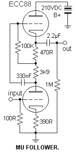
I have build an ECC88 mu follower where i got the output impedance down to 140 Ohm.
You then have to run more idle current.
I find a mu follower a really good circuit :
High gain, high bandwidth and low output impedance.
It was used in output stages of measurement instruments from Rohde&Schwarz and Wandel&Goltermann.
It can drive a lower impedance but then distortion goes up.
I have build an ECC88 mu follower where i got the output impedance down to 140 Ohm.
You then have to run more idle current.
I find a mu follower a really good circuit :
High gain, high bandwidth and low output impedance.
It was used in output stages of measurement instruments from Rohde&Schwarz and Wandel&Goltermann.
The problem with the SRPP (and hence mu-follower) formula on the linked page is that the author appears to simply put the upper and lower arms in parallel and assume that this is the output impedance. He doesn't take account of the lower valve driving the upper valve, which is the whole point of the circuit!
For the SRPP (and mu-follower) the output impedance and optimum load impedance can be (and usually should be) quite different. It is even possible (I think) to design an SRPP with an output impedance which exceeds its optimum load impedance - so you automatically get a significant reduction in gain when you load it optimally.
The SRPP can make a good amplifier when it is designed for a particular application. Sadly, what we mainly see is 'generic' SRPPs randomly scattered into (mainly Chinese) circuits as a fashion statement.
As I said, see the Valve Wizard for about the best explanation on the web.
Hi!
Do you actually read and think about the answers you get? Then it should be clear that a SRPP will probably not cut it either for your application
Yes, what about it? Why don't you sling your soldering iron and bang a SRPP together and just see how it works? Costs next to nothing and is a quick job
Thomas
Do you actually read and think about the answers you get? Then it should be clear that a SRPP will probably not cut it either for your application
What about an ECC88 SRPP?
Yes, what about it? Why don't you sling your soldering iron and bang a SRPP together and just see how it works? Costs next to nothing and is a quick job
Thomas
What about an ECC88 SRPP?
An ECC88 SRPP is quite a good output stage, and with a suitable transformer can drive 150 to 200mW into almost any load. It does however produce quite a lot of distortion so is best used in a negative feedback design. This circuit here will do that:
http://www.ianbell.ukfsn.org/EzTubeMixer/docs/EzTubeMixer/EurocardCCTsht3.jpeg
Cheers
Ian
Hi!
Yes that is putting in nicer words what I wanted to say. Didn't want to appear harsh. Remember that the answers you get will probably not be better than the questions you ask. You need to get over that first step to be able to ask good questions, only then you can make progress
Thomas
We help, but we don't do it for you.
Yes that is putting in nicer words what I wanted to say. Didn't want to appear harsh. Remember that the answers you get will probably not be better than the questions you ask. You need to get over that first step to be able to ask good questions, only then you can make progress
Thomas
Interesting circuit! The pot varies both open-loop and closed-loop gain - I assume that helps maintain stability?
- Status
- Not open for further replies.
- Home
- Amplifiers
- Tubes / Valves
- ECC88 mu-follower