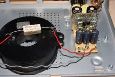
1ohm across the inductor took the worst of the deep humm
also tried various adjustments to the buffer
all seemed to work ok, and sounding a bit different
some gave more humm
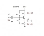
this one gives a voltage drop of 2.3V and 1.4V on collector and emitter
if I'm not mistaken it gives a current draw of 2mA on both sides
dont know if its good, but I like it
sound is responsive, crisp and clean
and most importantly, easily adjusted finding the right tone
also tried various adjustments to the buffer
all seemed to work ok, and sounding a bit different
some gave more humm
this one gives a voltage drop of 2.3V and 1.4V on collector and emitter
if I'm not mistaken it gives a current draw of 2mA on both sides
dont know if its good, but I like it
sound is responsive, crisp and clean
and most importantly, easily adjusted finding the right tone
Attachments
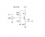
🙂 found what caused the excessive humm ('that wasnt there before') 
'turn on' resistor from supply/collector to signal input
with the orginally 60k mounted humm is almost gone
and most of the other snerring seem to come from instrument
regarding the power supply noise
now the inductor appears to do nothing good at all
only the 1ohm series resistor seem to works
and the actual sound also appear better with no inductor
will try make a small snubbered CRCRC board
Attachments
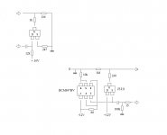
you need a DC block between the attenuator and the biasing resistors.
You will probably need a smoothing cap across the 22k to attenuate 13Vdc ripple.
You will probably need a smoothing cap across the 22k to attenuate 13Vdc ripple.
the 22k+60k bias resistors will apply ~2.8V across the Vbe+680r.
Bias current will end up @ ~4.2mA.
That current will drop ~4.2V across the collector resistor leaving Vce @ ~[13 -4.2 -2.9] =5.9V
Your multimeter should be able to confirm the actual voltages and let you calculate the actual currents.
Your multimeter may also be able to measure the ripple on the 13V supply and if it's bad then also at the 22k.
Last edited:
ac ripple is 7mv(0.007V)
voltage drop have changed after increasing 60k bias resistor
collector voltage drop is now 1.52V, and emitter 1.57V
(measured across resistors, and with measured 13.45Vdc supply voltage)
btw, voltage drop on 60k bias res was measured 1.67V
voltage drop have changed after increasing 60k bias resistor
collector voltage drop is now 1.52V, and emitter 1.57V
(measured across resistors, and with measured 13.45Vdc supply voltage)
btw, voltage drop on 60k bias res was measured 1.67V
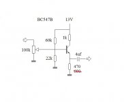
Some of your bias voltage is leaking out into the attenuator.
You must DC block the input between the attenuator and the bias resistors.
You must DC block the input between the attenuator and the bias resistors.
that 7mV will be reduced to about 2mV at the bias point.
That 2mV will appear on the output.
Signal to hum ratio will be terrible.
Fit a cap to smooth the bias voltage.
Possible reduce hum by 20dB and that will show as an improvement of signal to hum ratio of 20dB, try 100uF 25V.
That 2mV will appear on the output.
Signal to hum ratio will be terrible.
Fit a cap to smooth the bias voltage.
Possible reduce hum by 20dB and that will show as an improvement of signal to hum ratio of 20dB, try 100uF 25V.
when I changed the att pots from 10k to 100k suspected this
I cut the connection, so its now easy to mount dc blocking caps
will try it now
(but feels a bit stupid since there are caps before the att pots)
I cut the connection, so its now easy to mount dc blocking caps
will try it now
(but feels a bit stupid since there are caps before the att pots)
Hi tinitus, was just checking in on your BJT progress. You mentioned that you wanted to build it as a buffer, so I was wondering what the 1k on the collector is there for. Had assumed you were going originally for an emitter-follower arrangement? Maybe you are going for something else, but the input impedance on the circuit you have could be made a lot higher..
just needed a 2 channel output asap
but I really didnt expect it would work at all 😀
but now it works
so why try and learn something
so, please, feel free to try and teach me
but Im probably hopelessly lost
I still plan to build my 'juma' curcuits
but learning a bit first wont hurt
but I really didnt expect it would work at all 😀
but now it works
so why try and learn something
so, please, feel free to try and teach me
but Im probably hopelessly lost
I still plan to build my 'juma' curcuits
but learning a bit first wont hurt
Attachments
... I was wondering what the 1k on the collector is there for.
I thought it should be there for bias stability
but just now read it might be better to use symmetric +/- supply
and connect emitter to negative
oh, btw, since I have 13V, I thought it could be fun to try it with a big dry cell 12V battery
and convert the power supply to a small battery charger
through all my searches recently, I have noticed a lot of fun looking helper curcuits to monitor batteries etc
noticed a book called 'talking...'...something, with loads of weird curcuits for all kinds of 'hobbies'
and convert the power supply to a small battery charger
through all my searches recently, I have noticed a lot of fun looking helper curcuits to monitor batteries etc
noticed a book called 'talking...'...something, with loads of weird curcuits for all kinds of 'hobbies'
Hi Tinitus, OK if you want to try classic emitter follower, looking at your previous circuit I would make following suggestions. Note that you won't get voltage gain off the emitter follower circuit but you will get higher input impedance, and get more current drive capability at the output (example to drive a tone stack etc) without loading the source signal .
Eliminate collector resistor and tie in collector direct to 13 Volt Rail. Increase Emitter resistor to about 2.5 to 3 K. You can calculate the upper resistor in your biasing to apply enough bias current, or just try a 250K variable trim pot ( as variable resistor). You can eliminate the lower biasing resistor. As AndrewT said you need a input decoupling capacitor, and I would move the attenuator to the output of your circuit after the capacitor there, a 10 K audio taper would be fine.
Eliminate collector resistor and tie in collector direct to 13 Volt Rail. Increase Emitter resistor to about 2.5 to 3 K. You can calculate the upper resistor in your biasing to apply enough bias current, or just try a 250K variable trim pot ( as variable resistor). You can eliminate the lower biasing resistor. As AndrewT said you need a input decoupling capacitor, and I would move the attenuator to the output of your circuit after the capacitor there, a 10 K audio taper would be fine.
.... move the attenuator to the output of your circuit after the capacitor there, a 10 K audio taper would be fine.
means I could also place it after my high-z input jfet, and a buffer would be pointless 😕
but wouldn't that need a poweramp with tube like high impedance input
right now I use old LC Audio solid state
it was said to have 4k input impedance
I remember this because I once considered a tube preamp
but was told that due to impedances the preamp output cap would need to be insanely big
I have also thought about trying transformer output/splitter
maybe even balanced
but not before I have a properly working preamp
Hi Tinitus, OK if you want to try classic emitter follower...
have read its not 100% stable, and is less reliable
I made mine from what I understand is 'autobiased'
changes will take away the 'bias compensation' effect
noise is actually not so bad
my commercial effect units are way more noisy
and really poor sounding in comparison
I am sure what you have will sound pretty good. Although 4K input on the LC Audio would be pretty low, the buffer could still drive it. No need to worry too much about stability on the common emitter in BJT. Just need decent stability on the supply. The Vbe will not drift enough to give any problem to operating point in a small signal buffer. That is a good advantage of BJT with regard to this case. Just suggestion..the CRC you were going to put in should be fine working with this.
When considering a tube preamp the output caps are generally not large from value of capacitance, it's the DC rating that makes them bigger. You would need a rating of at least 400 volts DC to block the 200Vdc or so. that would be big yes, not too big. But I would agree to considering a signal transformer, the signal voltage swing from tube based preamp can be almost an order of magnitude higher then transistors running at 12 VDC.
When considering a tube preamp the output caps are generally not large from value of capacitance, it's the DC rating that makes them bigger. You would need a rating of at least 400 volts DC to block the 200Vdc or so. that would be big yes, not too big. But I would agree to considering a signal transformer, the signal voltage swing from tube based preamp can be almost an order of magnitude higher then transistors running at 12 VDC.
No, actually it is an excellent way to deal with both input and output. The Hi z input jfet with an emitter follower after is in fact the best combination IMHO. The Hi z takes care of your passive pickups, no loading or high frequency dropout. The emitter follower BJT will hardly load down the jfet, but it can give you current drive capability. No voltage gain but it can cope with output loading much better.means I could also place it after my high-z input jfet, and a buffer would be pointless 😕
- Status
- Not open for further replies.
- Home
- Live Sound
- Instruments and Amps
- Switchable Hi-Z input impedance, how ?