Pieter Treurniet's reply:
then why did you come up with that Pimm graph, as it apparently gives no information on non loaded transformers below 100 Hz?
I just quote this because, again, it's wrong and proves you are not credible. I gave this info in my first post in this thread! The Pimm graph came into play as you criticized Lundahl products.
Else, I really don't care what you think, what you say and what you do and I am certainly not willing to help you to understand! Certainly you cannot stay away from this forum. A proverb says " the one who despises just buys!".
IF YOU KNOW...
...someone that has a pair of 801A for sale, please tell me 😀
I put my request on "Swap meet" but maybe looking at this thread...
...someone that has a pair of 801A for sale, please tell me 😀
I put my request on "Swap meet" but maybe looking at this thread...
I just quote this because, again, it's wrong and proves you are not credible. I gave this info in my first post in this thread! The Pimm graph came into play as you criticized Lundahl products.
Else, I really don't care what you think, what you say and what you do and I am certainly not willing to help you to understand! Certainly you cannot stay away from this forum. A proverb says " the one who despises just buys!".
I think you did a great job by explaining some misconceptions.
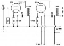
SE CONCEPT 801A
The project is going slowly. I still don’t have all the parts yet (it’s faster to get a box from Europe than USA unless you’re ready to pay an outrageous price!). Finally decided to choose 6A6s instead of 6N7Gs because it’s easier (and cheaper) to get them.
For design details, please refer to Thomas’s blog:
VinylSavor: Single Ended Amplifier Concept, Part 6
It took time to make up my mind but after reading the SE concept articles and some other experiments (audio-talk :: View topic - 801A SE), I decided to stick on Vinylsavor DHT SE.
Description:
R1= 200k (on hand)
R2= 1k, 1W
R3= around 1.5k (between 1.2k and 1.8k), 5-6W
C1,C2,C5= combination of 10, 22, 47 and 50 µF (Solen caps on hand bypassed by 0.1 PIO and BTW Solen Canada isn’t that far…)
C3,C4= 100-200µF. I’d put OS-CON there but the voltage is too high at C4 for what I can have around here. However, Nichicon and Panasonic make also polymer caps easily available at 50-63V rating. It’s also possible to put a big Solen 100µF (or maybe a smaller value) if I have the space. All bypassed PIO also.
801A and 6A6 HV: two Tom Cr. Maida regulators will do the job. Probably a choke filter (or power resistor) will be used to reduce the voltage for the 801A power supply since I have around 685V raw DC (don’t like the idea of a very big heatsink on the MOSFET). Since the main transformer is CT, the “0” goes for 6A6s supply that only needs 300V (half of high voltage).
801A and 6A6 heater: both DC regulated (LT1083). Slow ramp. In the case of 801A, I wired two 5A dual bobbins transformers in series for that purpose.
OPT: big Electra-Print 10K/6s I have will be wired (but meant for my 211 amp).
Attachments
Hi!
If you want to use regulated filament supplies, I strongly recommend to use current regulation. The 801A is extremely sensitive to the filament supply. The filament supply is very audible with this tube. The Coleman regs should be a save bet. I still prefer the passive approach with LCL filters.
Best regards
Thomas
801A and 6A6 heater: both DC regulated (LT1083). Slow ramp. In the case of 801A, I wired two 5A dual bobbins transformers in series for that purpose.
If you want to use regulated filament supplies, I strongly recommend to use current regulation. The 801A is extremely sensitive to the filament supply. The filament supply is very audible with this tube. The Coleman regs should be a save bet. I still prefer the passive approach with LCL filters.
Best regards
Thomas
filament regulator
Actually, I took the design on Pete Millett's website:
Regulated DC filament supply
Actually, I took the design on Pete Millett's website:
Regulated DC filament supply
I haven't tried this particular design. But in my experience voltage regulated filament supplies can ruin the sound.
Thomas
Thomas
filament supply
A "passive approach" means something similar at.. VinylSavor: Making of a 211 Amplifier, Part 1: Planning ?
It looks like one of the 211 monoblocks filament supply could be used for two 801As but the inductance seems pretty high (100 mHy)...I saw choke values between 10-20 mHy for 801A.
A "passive approach" means something similar at.. VinylSavor: Making of a 211 Amplifier, Part 1: Planning ?
It looks like one of the 211 monoblocks filament supply could be used for two 801As but the inductance seems pretty high (100 mHy)...I saw choke values between 10-20 mHy for 801A.
Hi!
Yes, but if you are on a budget or space is restricted use the Coleman regs.
I use Lundahl LL2733 filament chokes. For the 211 they are wired in parallel due to the high current. For the 801 they can be wired in series for 400mHy. I want lots of decoupling from the power supply. You need separate filament supplies otherwise the tubes will not bias independently any more.
Best regards
Thomas
A "passive approach" means something similar at.. VinylSavor: Making of a 211 Amplifier, Part 1: Planning ?
Yes, but if you are on a budget or space is restricted use the Coleman regs.
It looks like one of the 211 monoblocks filament supply could be used for two 801As but the inductance seems pretty high (100 mHy)...I saw choke values between 10-20 mHy for 801A.
I use Lundahl LL2733 filament chokes. For the 211 they are wired in parallel due to the high current. For the 801 they can be wired in series for 400mHy. I want lots of decoupling from the power supply. You need separate filament supplies otherwise the tubes will not bias independently any more.
Best regards
Thomas
cathode resistor
Thomas (or someone else),
What value did you put in your 801A amp?
Did you try some values of bypass cap?
Thanks
Pierre
Thomas (or someone else),
What value did you put in your 801A amp?
Did you try some values of bypass cap?
Thanks
Pierre
Hi!
I didn't read the title, sorry.
try 1.5k. Leave C4 out and try. You shouldn't need it
Best regards
Thomas
I didn't read the title, sorry.
try 1.5k. Leave C4 out and try. You shouldn't need it
Best regards
Thomas
testing 801A
I wanted to test the output tubes (801A) so I attached a 375k resistor from ground to the grid (no input tube connected). Is the value ok?
Thanks
Pierre
I wanted to test the output tubes (801A) so I attached a 375k resistor from ground to the grid (no input tube connected). Is the value ok?
Thanks
Pierre
Hi!
Check the tube datasheet for the max allowed grid to ground resistance. 500k for cathode bias. 100k for fixed bias. For testing you can also connect directly to ground, assuming you have a cathode resistor installed
Thomas
Check the tube datasheet for the max allowed grid to ground resistance. 500k for cathode bias. 100k for fixed bias. For testing you can also connect directly to ground, assuming you have a cathode resistor installed
Thomas
Hi!
Check the tube datasheet for the max allowed grid to ground resistance. 500k for cathode bias. 100k for fixed bias.
I did. But an experienced person's advice is always welcome.
For testing you can also connect directly to ground, assuming you have a cathode resistor installed. Thomas
Ah! I didn't know that. Yes I have a 1.5K installed. Thanks again.
Choke for 6N7?
Hi. I was thinking to add a choke for the 6N7 line filter but they only draw few mA. Do you think it worths the "effort"?
Thanks
Hi. I was thinking to add a choke for the 6N7 line filter but they only draw few mA. Do you think it worths the "effort"?
Thanks
Hi Pierre,
I do it in my more elaborate amps. But that is more for the piece of mind. I would first built it with the RC decoupling stage. Once that works you can still experiment with a choke
Thomas
I do it in my more elaborate amps. But that is more for the piece of mind. I would first built it with the RC decoupling stage. Once that works you can still experiment with a choke
Thomas
Change
I'd like to look for a different HV line filter for the 801A. The MOSFET in my regulator blown...Voltage too high. Would have to change some part values. Actually, it would need a power resistor just before the regulator but a lot of energy would be lost. Since I have already a Hammond 193C (20H, 100 mA, 600V) I could try a LCL (with a small cap after the bridge) using it as a second choke. However, looking at other Hammond chokes, I would have to put two in series to get a "first choke combo" that holds the voltage.
Does someone have another suggestion?
Thanks
- Status
- Not open for further replies.
- Home
- Amplifiers
- Tubes / Valves
- 45 amp with 6N7