I know how install the potentiometer but I see at audio-gd another way and supposed improved to connect the pot, is OK? the resistor value have to be 20% of pot value or other value?
TIA
Felipe

TIA
Felipe
Each solution has its place. The first provides relatively constant high load resistance to the previous stage, but variable source resistance (that could go up to as high as 25k) for the next stage. The second has variable load for the previous stage (that could go as low as 20k), and relatively constant low source resistance for the next stage, but you will have some attenuation at max volume. The second version has less noise due to lower resistance at the input of the next stage.
So it depends on the driving and load requirements which is the better topology. Ideally the value of the potentiometer should be > 10x the source resistance, and < 10x the load resistance. That means the souce resistance should be < 10k, and the input resistance of the next stage should be > 1M, as typical for tube amplifiers.
Don't get fooled by any explanation about shorter/straight signal path
It is not possible to answer your question without knowing:
- the output impedance of the stage driving the volume pot
- the minimum allowed load impedance of this stage
- the input impedance of the next stage
- the maximum allowed source impedance for the next stage
- signal level (for noise aspect)
In general, the lower serial resistance is the better, if the previous stage tolerates it 😉 Are you sure this is the optimal topology for your application?
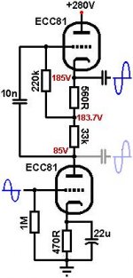
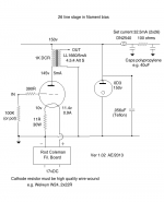
One case for ECC81 mu-follower, other case for #26 preamp, mu follower driving headphones 300 ohms, #26 preamp driving SS 100k input impedance
Wich resistor value is necessary for 2nd pic?
Too load at max volume? Then perhaps you can lower the gain of the first stage. Easiest way is to remove the cathode resistor... Or use a simple cathode follower. Have you seen somewhere these three parts (preamplifier, volume control, power amplifier) recommended together?
- Status
- Not open for further replies.
- Home
- Source & Line
- Analogue Source
- ALPS RK27 100K log dual