Hello Big John
I know the M40 pretty good and restaured some of it.
How I proceed:
- replace the Selen-rectifiers (Selen gleich-riecht-er) by silicon rectifiers
- replace the electrolytic caps in the power supply chain. Jan is a good source, you can use 100+100uF instead of 50+50. Choose 400V, better 450V types (idle voltage with silicon rectifiers)
- now, you have higher voltage because of the silicon rectfiers. I normally insert another 100uF cap and a resistor between the rectifier and the existing PSU
- attach a dummy load to the speaker outputs and measure all voltages (Ub, Ua, Uk, Ug). This is showing you possibly faulty caps or resistors. The mustard caps in my opinion are generally still reliable.
When you want help in my workshop nearby Bern, you can send me a PM.
Regards
Franz
OK, so I'm working on the dead 40, put in new caps from Jan, and replaced the high voltage rectifiers with UF4007s. The voltages are off of one can and low off the other, but I'm still too green to understand exactly what to do to drop/boost them. I didn't replace the little 24v rectifier yet, and sure enough it's only putting out 17v. From the schematic I'm getting A=333 (300), B=336 (300), C= 300 (250), D= 211 (235), E= 169 (185), and F= 158 (170). In parenthesis are the volatages from the schema.
The old rectifiers were literally melted inside.
Nothing seems to be getting too hot, but the OPTs hum, and hooking it to speakers reproduces that hum with great fidelity and volume 🙂. As a dummy load when checking I am just using a 10w 4.7 ohm resistor in each speaker out- is that OK?
What's the next step? I'm green, I know, and don't mean to clutter the board with dumb questions- but I do have an RCA Recieving Tube manual on the way and have been avidly reading as much as I can online- I'm trying really!
Where is Uk (not the island)?
Replace the low voltage (24V) rectifier and caps first and retest.. In addition to providing filament power to the phono pre-amplifier it also provides the bias to the output stage.
C23 is shown as 3 x 600uF, however this would have been close to the largest reasonable value available at the time - this was used in ReVox G36 as well incidentally, however in this application you can replace it a 2200uF or even a 3300uF with some benefit. You may need to add a small amount of resistance in series with the transformer winding and ahead of the rectifier to get the voltage down to 24V. (I would estimate a few ohms to start and then adjust accordingly) You should use a small power resistor of a couple of watts rating for this purpose.
Uk is German for cathode voltage.
Last edited:
Leave it alone!
Hey Big John,
I believe in the old saying "If it ain't broke, don't fix it". The model 40 is a super classic tube amp that needs very little tweeking since it was designed for a looooong and sweet sounding life. It's a pitty to chop one up, especially given their rarity. But in the event you continue your modification experiments, get an isolation transformer so you don't end up on your butt again!
Hello from Paul and Phil.
BTW, Just bought a vintage pair of Klipsch Herseys. With 10 watts of tube power, they rock.
Cheerio, Big Ron
What a fascinating amp. That build style is something I have never seen but I like it. Do you suppose that those radial tag boards were made by Revox themselves or was that a standard hardware item? Would love to try something like that in a future build.
What a fascinating amp. That build style is something I have never seen but I like it. Do you suppose that those radial tag boards were made by Revox themselves or was that a standard hardware item? Would love to try something like that in a future build.
I've worked on quite a few ReVox decks and a few other products and have never seen exactly these particular socket mounted tag boards in anything else.
And they are an absolute PITA to work on, and you'd think the variety of materials used over the years would be heat resistant wouldn't you? Well they're not, the terminals will melt right out of the board if you dwell over long with yon solder iron. (For example when trying to remove the lead from a previously snipped part.) I tack solder to these, and in more inaccessible locations - and there are a lot of these in the G36 I am most familiar with I cut the leads at the component body and solder the new parts to the old leads, looks unprofessional to put it charitably - and that runs totally against my grain..
Have I said enough? 😀 Obviously I detest them.. 😀 😀 Love the G36 though!
That's too bad. They look like a fantastic way to organize parts right near their functional location rather than strung out along the underside of the chassis. Ah well. A lot of clever ideas have problems in actual application.
Hello all,
Sorry to revive and hack an old thread for my first post but thought it was better than to start a new one as much of the information I need is relevant to this thread.
I have a Revox Model 40 amp which I have owned for at least 25 years. I had it in daily use until maybe 17 or 18 years ago when one day it fizzed, crackled and then started smoking! I put it away with the intention of one day getting it repaired or repairing it myself. Well, that day has now arrived. I am not totally green to valve amps having done a few mods to my Epiphone Valve Junior guitar amp but do realise that a VJ is not in the same league as this Revox. I would like to do as much of this myself as is possible with my limited knowledge and I am very aware of the high voltages.
Anyhow, looking inside the amp there is no (visual) evidence whatsoever of any problems. Like I said, there was smoking coming from the amp but there is nothing to show where it was coming from. I had always assumed I had blown the output transformer as I was running 4ohm speakers at the time but now I'm not so sure.
My intention is to replace the bridge rectifiers first and then the large can capacitors but before I make a start I just wondered if anyone had any idea which component it was that would have been smoking? All the valves are the original Philips ones and look good. In face every component in there is the original one!
The amp hasn't been switched on since this incident by the way, 17 or 18 years ago and I don't fancy putting electricity through it until I know it's not going to explode on me!
Thanks in advance,
Ian.
Brockyman: Can you get your hands on a variac? If not, are you familiar with the light-bulb trick of wiring a light bulb in series with the power cord for troubleshooting?
Thanks for replying, much appreciated.Brockyman: Can you get your hands on a variac? If not, are you familiar with the light-bulb trick of wiring a light bulb in series with the power cord for troubleshooting?
I do not have a variac and whilst I know of the light bulb trick I have never done it. So my answers should probably be be No and No.
What are you thinking? (promise I won't do anything silly!).
Ian.
Brockyman: I'm certainly no expert, but there are several who have posted on this thread so I'm sure that you will get some good guidance.
I would start by pulling all of the tubes, verifying that the correct fuse is fitted and perhaps rigging up a lightbulb-cord setup if you have stuff laying around.
Do you have some 8ohm power resistors that you have connect to the speaker terminals?.....or perhaps some junk speakers? You typically don't want to power up a tube amp without a load on the outputs.
If it has been sitting for years, the caps may be unhappy if you whack them with mains voltage instantly.
For first power-up (even with the tubes removed) the white knuckle factor is reduced with a light-bulb, or at least the reassurance that the proper fuse is installed.
Do you have a multimeter? Do you have any clip leads or just probes?
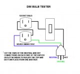
It's best to get a good used 5-10A variac then use the dim bulb tester in series to the unit being tested. You can probably start with a 100 watt bulb. You may need 60 & 150W bulbs to try.
You want to use the bulb to give an indication if you have a short or bad cap etc. when bringing up the voltage slowly. If you don't have the bulb you won't know if you have a short!
The bulb should glow brightly then fairly quickly dim as you bring the voltage up.
Be carefull not to break the bulb as contacting the broken filament could kill. Maybe use a trouble light shield etc.
Also always have a load on the speaker terminals (16 ohm 25W + resistors or cheap speakers) even when testing or you risk the output transformers.
Compact Dim Bulb Tester Wiring - AudioKarma.org Home Audio Stereo Discussion Forums
Here's another interesting tester:
Christy Electronic Tester
Attachments
Last edited:
You should assume that the main electrolytic caps will need reforming after all this time unused, but they might not be the cause of the original fault. Smoke suggests resistors or transformer trouble. A careful visual inspection is the place to start.
A lamp limiter will give some protection when first turning on, but it can't do miracles so be prepared to switch off if you smell, hear or see anything untoward.
A lamp limiter will give some protection when first turning on, but it can't do miracles so be prepared to switch off if you smell, hear or see anything untoward.
I would start by pulling all of the tubes, verifying that the correct fuse is fitted and perhaps rigging up a lightbulb-cord setup if you have stuff laying around.
Do you have some 8ohm power resistors that you have connect to the speaker terminals?.....or perhaps some junk speakers? You typically don't want to power up a tube amp without a load on the outputs.
If it has been sitting for years, the caps may be unhappy if you whack them with mains voltage instantly.
Do you have a multimeter? Do you have any clip leads or just probes?
Thanks. I will make a bulb tester from parts I already have. Looks very straightforward. I have resistors too so will rig up some dummy loads with some banana plugs. I do have a multimeter and clip leads.
As for sitting for years I was having a think about that and if I remember rightly I probably last used this before my children were born. My son is 24 next month so it is probably more like 25 years since it was last plugged in. Been well stored though at the back of a wardrobe, much to my wifes annoyance.
It was the fact that I was using 4ohm speakers which made me assume I had blown the output transformer.
Also always have a load on the speaker terminals (16 ohm 25W + resistors or cheap speakers) even when testing or you risk the output transformers.
A thorough visual search reveals nothing, everything looks as it should.You should assume that the main electrolytic caps will need reforming after all this time unused, but they might not be the cause of the original fault. Smoke suggests resistors or transformer trouble. A careful visual inspection is the place to start.
Thank you all for the input, it is much appreciated.
Ian.
hi, I am French and more experimented in transistors that bulbs. It my first post on this topic, so I thanks you for your undestanding.
I found a REVOX A40 amplifier; It sounds very good but is warming dramatically...I look inside : the original rectifiers have been replaced by silicium, so tensions are much more high :
A is 335v instead of 300v
B is 325v instead of 300v
C is 278v instead of 250v
D is 264v instead of 235
E is 214v instead of 214 v
F is 198v instead of 170v
all that is too high according the value on schematic diagram; I think that some differences (A and B, for example) are explained by not replacing filters capacitor. it is my project. But when I do this, I thing that all the tensions remain too high.
So, my question is how to obtain the good ones . I think I have to use resistors, but which value and to which place??
And my english is not very good...
The ideal will be annotations on the schematic diagram....
Thanks to those who read me!
- Status
- Not open for further replies.
- Home
- Amplifiers
- Tubes / Valves
- Revox Model 40- leave it alone or dig in?