Hey guys! I know there are a few threads out there but non seem to be for this... I am DIY-ing my own subwoofer, with this woofer, Reference 1060w - Infinity . Going to use it for mostly music and some movies.
I hoping to build a amp, which can handle about 200W of power(although I do not need so much) so that I can move this subwoofer to a larger room if needed. In the design it will have a 18hz HPF and a 250Hz LPF, for the LFE input and also a crossover and gain knob for the normal line input.
Which chip amp is best for powering this subwoofer? 4Ohm load
I am looking at the LM3886 but I am going to have to put them in bridge + parallel mode since it is only capable of
68W Cont. Avg. Output Power into 4Ω at VCC = ±28V
May I also know how to determine what is a good supply voltage (Vcc) for the power amplifiers chip?
Please do be patient with me as I am only an average in electrical stuff
Thanks
Last edited:
Buy one of those "epic" TDA7293 bridge amps they sound pretty neat really...
Class D would be best solution in your case, high power and low heat dissipation.
If you want to build all by yourself then im not very sure about class D anymore.
Maybe TDA8954 puts out around 200W in mono mode, simple to build too.
100W of pure power is insane overkill, i have 8950 in mono with 8R 12" Sub in Tline it just goes P-P at 100W.
Last edited:
In practice you will really only need two in parallel and you can have ±40V rails, or maybe even a touch higher at 42V. This will be approximately what you get from a 30V transformer. If you are doing a Linkwitz transform you will tend to run out of excursion before your amp runs out of puff - and if not, you have enough power to match the speaker levels in most instances.
Generally these subs have a DCR of 3.3 ohms or so for their 4 ohms nominal, so you are getting more power than the 4 ohm figure. In fact, from experience, I doubt you will even need to put two in parallel. This is an easy solution, and you can build two channels which you can parallel if needed. And, if you really want to go for the big power you can build the same again and do your bridging.
Finally, do make sure that the amp doesn't have any oscillations, otherwise it will get hot at these voltages. Personally I would put 100uF or more in a good quality electrolytic cap across the rails at the amplifier (ie close to it), be careful of your ground paths and have these two caps common before they go to the common ground. You may also want to put 100nF to 1uF in parallel with these electrolytics as well. And if you have a zobel, it must go back to the common ground, not be across the terminals.
One thing more. A 300VA transformer will only move about 1V in practice. You may want to choose something smaller so that it sags deliberately and makes things a bit easier for the chip.
Last edited:
Buy one of those "epic" TDA7293 bridge amps they sound pretty neat really...
Class D would be best solution in your case, high power and low heat dissipation.
If you want to build all by yourself then im not very sure about class D anymore.
Maybe TDA8954 puts out around 200W in mono mode, simple to build too.
100W of pure power is insane overkill, i have 8950 in mono with 8R 12" Sub in Tline it just goes P-P at 100W.
Thanks for the reply!
Class D is a total headache for me until I read more about it it's a no go. Unless it's a Class T which is much easier, but usually their power are too little for a single package.
Maybe I really dont need such a high wattage after all.
In practice you will really only need two in parallel and you can have ±40V rails, or maybe even a touch higher at 42V. This will be approximately what you get from a 30V transformer. If you are doing a Linkwitz transform you will tend to run out of excursion before your amp runs out of puff - and if not, you have enough power to match the speaker levels in most instances.
Generally these subs have a DCR of 3.3 ohms or so for their 4 ohms nominal, so you are getting more power than the 4 ohm figure. In fact, from experience, I doubt you will even need to put two in parallel. This is an easy solution, and you can build two channels which you can parallel if needed. And, if you really want to go for the big power you can build the same again and do your bridging.
Finally, do make sure that the amp doesn't have any oscillations, otherwise it will get hot at these voltages. Personally I would put 100uF or more in a good quality electrolytic cap across the rails at the amplifier (ie close to it), be careful of your ground paths and have these two caps common before they go to the common ground. You may also want to put 100nF to 1uF in parallel with these electrolytics as well. And if you have a zobel, it must go back to the common ground, not be across the terminals.
One thing more. A 300VA transformer will only move about 1V in practice. You may want to choose something smaller so that it sags deliberately and makes things a bit easier for the chip.
Linkwitz transform!! Genius! Why couldn't I find a EQ like that. Time to change my ported design to a nice little seal sub and maybe buy a larger woofer the Infinity 1260W.
Your post really enlightened me, thanks
Yes, I am most likely putting a zobel circuit, will take note of the grounding.
Btw, how do you calculate the max power needed for maximum excursion using a linkwitz transform circuit?
I did it on winisd, using paramatic eq boosts circuits to compare with linkwitz. It was about a good 10db of boost, means 10times of power inputed in winisd, hopefully this is a good gauge of power
Hope you could help me with this one, I cant find it with google either.
Btw, how do you calculate the max power needed for maximum excursion using a linkwitz transform circuit?
Mostly you guess - then you find your guess is wrong!
Your driver actually has some excursion data so you could work from that. 6dB of boost will be twice the excursion and four times the power, though there didn't seem to be a vast amount of excursion available. The power needs rack up absurdly quickly and drive you to one of two conclusions - that you need 1500W and two 12in drivers to do it properly or that you're going to make do with something practical.
One way on the practical path is to make your Linkwitz transform circuit adjustable. IIRC one part of the network cancels your driver high pass and another part inserts the shape you want and you can arrange it so you can move this part with a potentiometer. It's some years ago but I'm pretty certain this is the way I did it, and it's what led me to the conclusions above.
On the power question, your figure is correct - as is mine - but the source material sort of tends to invalidate the implied conclusion. Also you seem to have a very efficient driver there, though I haven't worked out how it's so efficient. Usually efficiency is at the expense of extension. At a guess I wouldn't rely on getting more than half a useful octave out of a Linkwitz transform, though you may be lucky and get close to a whole octave depending on your needs. Incidentally, you can see where the resonance is on their graphs because that's the point below which the excursion stays the same.
Last edited:
Has anyone used a LME49810 for a subwoofer before?
Cos it really puts out lots of power, anyone guide me in the right direction?
Cos it really puts out lots of power, anyone guide me in the right direction?
Keep in mind that this driver was intended for car sub use.
the graphs show in-car (witch car? size of the trunk ? 😀) and out of car (free space? half space? out of the car where? ) freqvency response.
most likely used in a room the out-of-car graphs are the ones to look at.
That leaves only the ported design to be acceptible, but even that has a -3dBL point near somewhere ~35 hz. ( a 25 usd value proper 7" er will actualy manage this too. )
in a car the sub gets quite a big gain, compared to room use.
(the plots sorthof show this quite well in the datasheet)
Getting a car speaker to produce deep tones in a room may be a bit difficult.
If You do not mind with my best intention, i would advise You to look at other speakers -assuming You did not purchase thisone allready- more suited for in-room use.
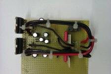
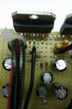
I came across these pics of my layout of the stereo/paralleled amps using the 3886 off 42V. They drove 2.7ohms quite happily and stayed perfectly cool. The topology is a bit different from the standard since they are driven differentially, so you'll need one fewer R and C on each side. You can count the holes to tell how big they are, but it's about the size of a credit card.
Attachments
Keep in mind that this driver was intended for car sub use.
the graphs show in-car (witch car? size of the trunk ? 😀) and out of car (free space? half space? out of the car where? ) freqvency response.
most likely used in a room the out-of-car graphs are the ones to look at.
That leaves only the ported design to be acceptible, but even that has a -3dBL point near somewhere ~35 hz. ( a 25 usd value proper 7" er will actualy manage this too. )
in a car the sub gets quite a big gain, compared to room use.
(the plots sorthof show this quite well in the datasheet)
Getting a car speaker to produce deep tones in a room may be a bit difficult.
If You do not mind with my best intention, i would advise You to look at other speakers -assuming You did not purchase thisone allready- more suited for in-room use.
Hey! Thanks for the tip and I understand but sadly(well maybe not) I already bought one of these. However, I still think that it was a great buy at just a little less than 50usd.
Haha I guess an average car size not the big SUVs types 😉
I have modelled it in winisd and tuned it to give me a reletively flat response all the way down to 25+Hz vented design. But ever since I was introduced to linkwitz transform by ChristainThomas, I loved it and changed my sub to a sealed box(which is what I always wanted) small, space efficient.
Thanks again 🙂
I came across these pics of my layout of the stereo/paralleled amps using the 3886 off 42V. They drove 2.7ohms quite happily and stayed perfectly cool. The topology is a bit different from the standard since they are driven differentially, so you'll need one fewer R and C on each side. You can count the holes to tell how big they are, but it's about the size of a credit card.
These looks quite neat. I will definately read up more about the lm3886, it does wonders.
- Status
- Not open for further replies.
- Home
- Amplifiers
- Chip Amps
- DIY Subwoofer amp!