Useful stuff, thanks! I am apparently using the one with the asterisk and the way Jan describes. 😀
... which actually is the purpose of the XLR pin 1 - there IS NO 'pin 1 problem' just connect the screen, through pin 1, to both chassis, right where it is bolted to the case, et voilá there's your tunnel.
jan
Last edited:
Mind if I ask just how many of "those" you are close with?
N+1
Example: One ungrounded AV receiver with a grounded subwoofer. Chassis leakage at the AV receiver sets its chassis at 1/2 line voltage. Very small current through the transformer to ground on the other side. Shields in transformer. Unbalanced cables ( consumer, RCA subwoofer output) Source impedance maybe several hundred Ohms, load impedance 20K. The leakage gets mixed with the audio on a high impedance transformer. A low Z transformer requires an active circuit to drive it which A) is too expensive a solution and B) requires power supplies and approvals. Once the circuit is active we did not need a transformer BUT at 5X markup its too expensive a product to have a customer base.
So you're talking about grounding issues rather than noise picked up by the line.
Doesn't seem to have much to do with common-mode rejection vis a vis moving coil phono cartridges.
se
et voilá
Suppose you had 2 tunnels, and just one Pin-1 exit on either side
(sorta stiff neck vision)
Attachments

Last edited:
Useful stuff, thanks! I am apparently using the one with the asterisk and the way Jan describes. 😀
yes, it is a very good way. See below. However, -- and there is always a however -- There are many ways the shield can be connected to each other at both ends and thus be compromised in effectiveness; Pathways which are not immediately apparent to the eye [this relates to Demian's/1Audio comments]:
One is to have the ground wire on the ac power cord/plug put each end together.... only takes one pair in the entire system of equipment.
The other is paths to the chassis from transformers (leakage and field induced currents). Thx-RNMarsh


Last edited:
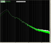
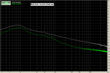
Some numbers regarding LF noise content of records
http://www.diyaudio.com/forums/analogue-source/96521-low-frequency-content-lp-vinyl-records.html#post1138292
attached are two snapshot from testings on my set-up 3 years ago. Pick-up point is the output of the RIAA preamplifier
(1 Khz reference tone 7cm/s modulation, reads –22db)
George
http://www.diyaudio.com/forums/analogue-source/96521-low-frequency-content-lp-vinyl-records.html#post1138292
attached are two snapshot from testings on my set-up 3 years ago. Pick-up point is the output of the RIAA preamplifier
(1 Khz reference tone 7cm/s modulation, reads –22db)
George
Attachments
Last edited:
Thank you Richard
Ref Fig. 6.19 (b) I still remember a professional tube microphone mixer/ pre.
Inside, there were braided twisted wires, having the braid soldered to the copper sub chassis every cm or less.
George
Ref Fig. 6.19 (b) I still remember a professional tube microphone mixer/ pre.
Inside, there were braided twisted wires, having the braid soldered to the copper sub chassis every cm or less.
George
Thanks Gpapag, It has been decades, since I had to take those pictures of a raw moving coil cartridge, but it looks right. I have to 'worst case' not 'best case' when I design.
Some numbers regarding LF noise content of records
http://www.diyaudio.com/forums/analogue-source/96521-low-frequency-content-lp-vinyl-records.html#post1138292
So these data are after RIAA equalization, and certainly point to the need for good overload margins (one of my reasons for using tubes). And they are consistent with my estimates for the extremely low levels of LF at the input. Thank you, George!
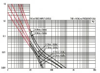
Looks to quadruple per octave, so 40dB/decade. 2.2% at -40dBu, 6.5% at -10dBu. Maybe 0.6% at -60dBu, using "typical" values.
Thanks,
Chris
Thanks,
Chris
Last edited:
Can anybody extrapolate the transformer distortion curve shown down to 2Hz? '-)
There you go.
Attachments
Last edited:
There you go.
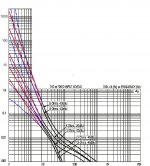
One step further 😀
The original –40dbu curves seem to me bending a bit downwards. The rest curves seem bending upwards. If this is true, it should show something like the blue lines. But real measurement data at theses frequencies may show totally different distortion (for better or worse).
For me UL signal distortion itself is not important. What I find of importance is the amplitude of the UL signal, as it (a) will eat up overload margin (b) will intermodulate with the audio frequencies.
George
Attachments
John, I can´t find the original post right now, but somewhere in this thread
you said:
"1933, mumetal transformer 0.1V out, 10 ohm drive, 50K load, 10Hz distortion is 0.072%.
1931, Amorphous transformer 0.1V out, 10 ohm drive, 50K load, 10Hz distortion is 1.2%.
This is a distortion increase of about 20 times between the two units.
13.5 mV drive voltage.
Your distortion may vary.
I am going to REMOVE the transformer."
I´m not sure if 0.072% for a warped record would be something to worry about,
but OK, let´s assume we use an amorphous core. How would we ever arrive at
0.1 V output from the transformer ?
Three points that make such a scenario unplausible IMHO:
1) A correctly set up tonearm cartridge combination should have a
resonance frequency of 9-12 Hz, frequencies below that point should
be attenuated 12 dB / octave.
2) 100 mV out from the transformer at 10 Hz will be amplified
approx. 60 dB by the subsequent RIAA stage (assumed 40 dB gain at 1 kHz)
this will (theoretically) result in 100V output. Actually the phono
stage will clip way before this point and will deliver a 10 Hz square
wave (almost) which will make your speakers disintegrate rather quickly.
3) A record which produces this amount of warp is not playable if it
exist at all.
Which transformers did you use, especially the amorphous core (from 1931 you mentioned - didn't know that they used amorphous that times).
And can you explain ypour measurements (circuit, signals, cartridges etc.).
- Status
- Not open for further replies.
- Home
- Member Areas
- The Lounge
- John Curl's Blowtorch preamplifier part II