Attachments
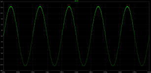
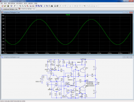
Judging by that output phase it's local oscillation of one of the output CFP's. One solution I've seen in this thread is to put a several nF cap across the B-E of one of the outputs. However C6 could simply be too large. The phase-lead cap should never be larger than it needs to be unless it has a series resistor.
It would be useful to see the circuit and conditions generating that waveformHi
it looks like oscillations but the great potential:
It would be useful to see the circuit and conditions generating that waveform
it is a curcuit from here: http://www.diyaudio.com/forums/atta...-cheap-circlophone-circlophone-darlington.asc
I only changed
step time to 1ns
start time 5ms
stop time 11ms
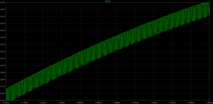
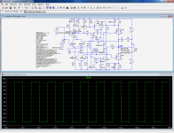
The parameters of the darlingtons differ from the CFP, which destabilizes the common mode loop.it is a curcuit from here: http://www.diyaudio.com/forums/atta...-cheap-circlophone-circlophone-darlington.asc
I only changed
step time to 1ns
start time 5ms
stop time 11ms
Problem can be fixed by adding small compensation caps to each OP transistor.
Attachments
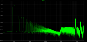
When I select 1K (instead of 1K2) for R6 and R7 in original schematic, THD is getting o bit lower in simulation. Can you clarify that how is it safe to use 1K (or lower) with 32V rails?
R6 and R7 steal some current from the bases of the VAS. If they become too low, the residual base current multiplied by the Hfe will become too low to drive fully the OP compounds.
The actual point at which it will effectively happen depends on a number of factors, mainly the Hfe of the transistors involved. Also, if the current becomes too low, this will be noticed by the common mode servo, and it will try to correct it by increasing the tail current of the LTP.
This means you can probably go rather low without the amp ceasing to function, but some characteristics might be degraded.
you can probably go rather low without the amp ceasing to function, but some characteristics might be degraded.
I never thought that their function is to steal some current, I actually thought that current direction is opposite. I'll stay put with 1K2's in case of whatever simulation shows.
Another thing is R values in compensations. Are their value mostly depends on the current where they suited rather than altering phase behaviour like corresponding C's? In short, we can alter the compensations without altering the R's, is it right?
Not very clear. Anyway to summarize, the R associated with the C creates an inflection point where the C action stops.Another thing is R values in compensations. Are their value mostly depends on the current where they suited rather than altering phase behaviour like corresponding C's? In short, we can alter the compensations without altering the R's, is it right?
You are free to experiment other values, there is some tolerance on each side of the optimum, and even if you go too far, you will normally not destroy anything
I'm still very interested to replace the Zeners with a transistor, except not the same as last time that made a kink in the treble as if the cap parallel to the feedback resistor quit working (weird and painful ear pressure--high treble went off the beam--feedback didn't work right). This time, I don't want to plug that transistor into the feedback loop. Is there a way?
Problem is, I hear no difference (OK, I have tin ears), and more worryingly the effect of the transistor is undetectable by measurements, and even more worryingly, the sim is unable to show any difference.I'm still very interested to replace the Zeners with a transistor, except not the same as last time that made a kink in the treble as if the cap parallel to the feedback resistor quit working (weird and painful ear pressure--high treble went off the beam--feedback didn't work right).
Without knowing exactly what effect is a problem for you, it is difficult to combat.
If you want to mimic more closely the effect of zener with a transistor, you can tie its base to the ground instead of the output.This time, I don't want to plug that transistor into the feedback loop. Is there a way?
This configuration is inferior in principle, but shows no practical difference.
I'm about to buy some BDY73's for my next Tringlophone project. It is more like a high Hfe version of 2n3055 (Vce=60V). Not a problem for single 32V rail. Datasheet graphs shows that It handles 70V if Rbe=1-100 ohms.
Since that Circlophone contains 15R at their 2N3055's B-E legs, can we assume that BDY73's suitable for using in Circlophone with 32V+32V rails? I just need some approval.
Since that Circlophone contains 15R at their 2N3055's B-E legs, can we assume that BDY73's suitable for using in Circlophone with 32V+32V rails? I just need some approval.
Attachments

In principle, no: the SOA only extends to 60V. The Vcer applies only when the transistor is off.Since that Circlophone contains 15R at their 2N3055's B-E legs, can we assume that BDY73's suitable for using in Circlophone with 32V+32V rails?
That said, they will certainly not blow into your face for a mere 4V excess....
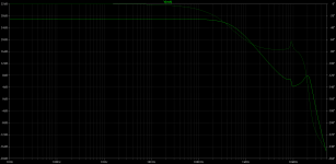
This message is for Terranigma: he has tried a darlington version, and has encountered some overshoot issues with a squarewave signal.
The problem is not very apparent in sim, anyway here is a logical path to a fix: increase C6 to 82pF for example (or any suitable value).
To avoid creating other problems, it could be wise to include a series resistor with the additional cap.
Here is the modified schematic (addition of C4/R2).
The value of R26 could also be tweaked (increased)
Adding a suitable input lowpass could also help (Fc~=200KHz)
Attachments
Overshoot
In addition to Elvee's comments on the overshoot issues:
Don't set the input filter to high this woud also add to the overshoot problem(s) especially when it comes to high slew square signals.
In addition to Elvee's comments on the overshoot issues:
Don't set the input filter to high this woud also add to the overshoot problem(s) especially when it comes to high slew square signals.
In addition to Elvee's comments on the overshoot issues:
Don't set the input filter to high this woud also add to the overshoot problem(s) especially when it comes to high slew square signals.
Don't set the bandwidth of the input filter to high....
Here is the modified schematic (addition of C4/R2).
The value of R26 could also be tweaked (increased)
Adding a suitable input lowpass could also help (Fc~=200KHz)
Adding a ~1.5 nF input filter cap completely took care of that overshoot issue for me. But this value is effective while using a 10K volume pot before amp. 2K5 pot requires ~3.9 nF for clean square waves. I don't know why. 10K seems to me not that out of spec at my setup. I used ~550 Hfe BC550C's as input transistors.
Higher R26 values and first attempts for adding extra network at feedback caused oscillations. I didn't try many combinations there and I settled with input filter method.
Thank you Elvee and Piersma.

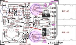
N-Darlington Output PCB Files
Hello All,
I consider that I finished my PCB layout of N-Darlington output version of vanilla Circlophone. I built two channels and they are running for a while. Purity, dynamics, punchy bass.. I think this version is no less than original output scheme. Even with those ST TIP142's. During first tests, I attached Philips BDV65B's and accidents costed 2 pairs of BDV's to me. Then I decided to use cheaply available ST TIP142's and I saw that nothing wrong with these ones. They perform really good and they feature much robust casing.
I used BD140's as servo transistors because mine were good quality ones from Philips and Harris. I measured their cb capacitance at 0V and Harris ones were always lower (35pf vs 52pf). Then decided to to use them although reputability of PH ones.

Edit... additional info from terranigma is here,
http://www.diyaudio.com/forums/soli...ssories-beginner-friendly-12.html#post3459051
Hello All,
I consider that I finished my PCB layout of N-Darlington output version of vanilla Circlophone. I built two channels and they are running for a while. Purity, dynamics, punchy bass.. I think this version is no less than original output scheme. Even with those ST TIP142's. During first tests, I attached Philips BDV65B's and accidents costed 2 pairs of BDV's to me. Then I decided to use cheaply available ST TIP142's and I saw that nothing wrong with these ones. They perform really good and they feature much robust casing.
I used BD140's as servo transistors because mine were good quality ones from Philips and Harris. I measured their cb capacitance at 0V and Harris ones were always lower (35pf vs 52pf). Then decided to to use them although reputability of PH ones.
Edit... additional info from terranigma is here,
http://www.diyaudio.com/forums/soli...ssories-beginner-friendly-12.html#post3459051
Attachments
Last edited by a moderator:
Don't just measure Ccb! Measure Cbe too. There are many low-Ccb transistors that have excessive Cbe. Never heard of Harris, BTW. Where do you get those?
Don't just measure Ccb! Measure Cbe too. There are many low-Ccb transistors that have excessive Cbe. Never heard of Harris, BTW. Where do you get those?
What at least I know about Harris is, they acquired RCA semiconductor. I think they were in production during 90's. I found those BD's from a local shop in NOS condition.
Ok, I did a quick test for Cbe:
Ph BD140 : 120pf
Harris BD140 : 150pf
Moto 2N3020(3019) : 65pf
Moto 2N2905A : 35pf
Ph 2N2905A : 30pf
Toshiba 2sc5171 : 645pF (16pF Cob spec'ed)
So, what this mean? Is Cbe a critical value for bias servo here? Do we consider that BD140 ones obviously out of spec?
Last edited:
- Home
- Amplifiers
- Solid State
- ♫♪ My little cheap Circlophone© ♫♪