jneutron,
Given that your solution was so elegantly done what of a standard situation where the center tap wire is not long enough to reach all the way to the capacitors and the bridge has screw terminals? Would you not still be able to braid the wires and extent the center tap wire, and what effect would the screw terminals cause?
Given that your solution was so elegantly done what of a standard situation where the center tap wire is not long enough to reach all the way to the capacitors and the bridge has screw terminals? Would you not still be able to braid the wires and extent the center tap wire, and what effect would the screw terminals cause?
The effect I speak of is independent of the transformer configuration. It is sometimes necessary to worry about the wiring inductances and the impact of changing current on a conductor.Question does this also happen with multi secondary windings ? Will a duel secondary with a derived center point have the same effect and how much . Yes it not a direct answer to the question but is an option if the transformer is not already in hand.
For a dual secondary, I'd twist the wires in pairs so there is no wiring coupling between. What happens in the core stays in the core, RN spoke on that.
jn
jneutron,
Given that your solution was so elegantly done what of a standard situation where the center tap wire is not long enough to reach all the way to the capacitors and the bridge has screw terminals? Would you not still be able to braid the wires and extent the center tap wire, and what effect would the screw terminals cause?
I tailored the description to the xfmr RN posted, where the wires were soldered to the terminals.
The concept is workable even if you have screw terminals. The principle is to keep all three secondary wires intimate with the ground, and both rails after the bridge the same. Keep all loops as small as possible. Extending the center wire via splice or terminal is not a big deal to the concept.
With discrete wires, the best you can hope for is an inductance reduction of about one order of magnitude. From 2 to 5 uH down to 200 to 500 nH.
My solution with copper foils and dielectric sheets was to get the inductance so low, and the capacitance so high, that I was able to eliminate capacitive bypasses at the chip amp. The inductance back to the supply caps was in the 10 nH range.
RN's depiction is interesting in that coupling internal to the xfmr would seem to be dependent on transient to conduction timing. I'm not sure from the waveform when within the cycle it was connected.
jn
Last edited:
Be delighted. I'm rather sickened by the crass intellectual dishonesty shown by some here- real discussion is so much more useful.
I'd start by looking at en plots of active devices. They all have a 1/f corner at audio frequencies. This is not surprising since shot noise is expected to have a 1/f characteristic. Likewise, we see a 1/f corner in any RC-coupled circuit. As well, the excess noise of resistors generally follows 1/f characteristics. These are dominant noise sources in analog audio electronics.
edit: note the noise spectra in this paper: https://dcc.ligo.org/public/0002/T0900200/001/current_noise.pdf
SY, thanks for posting this again. It basically shows that using good resistors well within their rating, above 100 Hz or so Johnson noise tends to dominate. The same goes for the sort of active devices I look at most, opamps. For a whole system, as I mentioned before, other noise sources such as PS hash and pickup come into play as well. So far, this confirms the measurements I have done, which might show some downward slope below 100 Hz or so, but subsequently get dominated by other factors. And even below 100 Hz, it is usually the PS residue which we have at 50 and you at 60Hz which towers high above it.
I don´t think this particular thread is best suited for an in depth discussion on 1/f and other noise sources in electronics. Perhaps we should move it to a new thread.
Maybe audiophile amps do things that audiophiles like very well.
Or cases of extreme perceived dissonance.
(one might check the audiophile's CD/LP collection as indication, plus an age count)
For the record:
The amplifier that SY continually brings up, DOES MEASURE LOUSY, and it is VERY EXPENSIVE.
Yet I once heard it at a CES, and it was the best sound of the show!
How can this be? Am I to praise another competitor's product over my own, just to be 'above the fray'? No, it REALLY SOUNDED GOOD, in that demonstration.
Now, how could it be good sounding in one demonstration, yet measure so badly?
That's a hard one, but I was there, so I also saw the equipment (fully horn loaded loudspeaker) first class vinyl record player, and a wonderful recording of Ella Fitzgerald singing 'September Song'. At least I think it was Ella. Now, how can I remember all that after 10 years passing of me dropping into a competitor's room to listen to the 'competition'? Was it distortion I was hearing? NO! It seemed to be one of the most natural human voices I have ever heard reproduced.
OK, you say, what about the distortion measurement at 1W, just 1W? Well, in my estimation, we were not playing anywhere near 1W, probably more like 1-10mW, with 100mW absolute peaks. The music was concentrated in the midrange around the human female singer's voice, no super lows or highs.
Now this is where audio engineering comes in:
If you are an engineer, you should be able to predict the distortion level from just about any measurement, at a specific level, both up or down in a class A system. I have textbook proof of this, even if many of you don't.
Now, a single ended tube IS CLASS A, by its very nature.
So, at 10mW (85spl let's say ) the distortion of the second harmonic would be 10 times less, the third harmonic 100 times less, etc. Now does that put things in the 'ballpark' of listenability? Of course it does. Next, let's say, being experimenters, the Wavac people played with the output polarity and found that connecting the all horn loaded speaker in one way, made it sound best? Why would this be so? Because the second harmonic would tend to cancel with the second harmonic naturally generated by the horn throat distortion. Wow! Better than a perfect amp in performance. '-)
Finally, the test waveform that makes the Wavac look so bad, even at 1W, is always 50 Hz! Maybe, that just saturates the transformers, and distortion at 100 Hz or above, might look much better. That is what I think made this very expensive, and in some ways a 'childish' contra-engineered design, sound so good in some situations, yet measure so bad in an engineering based test.
Now, how could it be good sounding in one demonstration, yet measure so badly?
Perhaps you just like high order distortion and roller coaster frequency response. Effects boxes do sell quite well and studios/musicians make frequent use of them.
For $350k, one ought to expect transformers that don't saturate at 50 Hz. But hey.... TEAM! Always an excuse.
Well everybody, I just reviewed the Wavac review, and I stand behind everything I said above.
Personally, I think this is a 'flawed' amplifier, but within its range of usefulness, it can be pretty darn good.
Unfortunately, the next year brought a completely different line-up of amps, speakers, and sources from Wavac, and it was pretty disappointing.
However, SY should not use this 'aberration' as representative of hi end amp design. It just does not fit.
Sy,
I am going to take a different approach to John's last post. In this one instance John has described how this obviously flawed design actually sounded good to him and perhaps many others in this one particular demonstration. Synergy would explain that in this one application. I will give it to John that he didn't bring in any fairy dust to explain what happened. He also knew that the design was flawed but in this one instance things just worked to make that particular album sound wonderful. At least he did try and come up with some plausible explanations of why it could have been so this one time. Doesn't mean the amplifier was anything but an exercise in horrible design but in this one instance with all of the exact parameters that happened in that room everything seemed to work for the music. Now change one thing and the whole illusion may have fallen apart like just raising the spl level or using a different speaker but this one time it worked. I do believe that John enjoyed that music, for whatever reason. And it does seem to me that he did recognize that the design was incorrect but could not find fault with that one demonstration. At least there was honesty in what he was saying, there was no magic bullet that made a bad design good, it shouldn't have sounded good but it did. Testing obviously showed the faults of the design and John acknowledged that and that is a much better position than using some statistical analysis that asks the wrong question. I'll leave it at that.
ps. I am sure if we pick his analysis apart line by line you can find fault, but the general explanation was at least an attempt to understand what may have happened in this one instance.
Last edited:
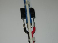
Here's a demo of what I meant. The white is CT, the blue wires are AC feed, the red is pos, black is neg. Note: I do not recommend simply tacking wires like that, but I had a GBU8K on my desk, so used it. Also, it's not necessary to keep this linear geometry, that was just for my convienience. White is #12, others are #14, so braiding or even bending wasn't possible while keeping the bridge leads straight..
Note the AC (ground) simply passes through the neighborhood. It goes directly to supply cap center. The ties keep the wire spacing minimal.
Note also that the triad grouping minimizes rail to rail inductance as well.
jn
Note the AC (ground) simply passes through the neighborhood. It goes directly to supply cap center. The ties keep the wire spacing minimal.
Note also that the triad grouping minimizes rail to rail inductance as well.
jn
Attachments
Last edited:
Looking around, about the progress in analog electronic, i was wondering why so little changes in hifi since 1970s. Fets, CMD, and lower price for metal film resistance, and then ? The most amazing are loudspeakers. Nothing new.with some lack of creativity
Christophe,
"So little change in hi-fi since 1970s". As an offer to get you up to speed on what has changed, take a look at these parts and see if you still can say the same.
Rohm BU9458
Silicon Lab Si4735 & Si4770
Analog Devices AD797
TI PGA2320
and the list goes on
Maybe not pure analog, in the true sense but the bottom line is that they all have analog signals as their outputs.
After all, what is your definition of Hi-Fi, I thought it was originally stated that it was for an amplifier that produces less than 1% THD.
Regards
Rick
Thanks to had explained the things in a such a clear and short way. Now, it makes sens.The amplifier that SY continually brings up, DOES MEASURE LOUSY, and it is VERY EXPENSIVE.
Yet I once heard it at a CES, and it was the best sound of the show!
jneutron, thanks so much for the explanation, that is very clean. so to summarize for the somewhat disabled, this arrangement is primarily to keep the loop area for parasitic inductive effects as small as possible, 'ground' impedance as low as possible, while also adding some small amount of capacitive decoupling for HF (or this is only when foils are used?)
We designed and sold a 2 x 50W customer AMP in 70, witch measured 0.05% of distortion and used fast power NPNs which had nothing to fear of modern ones about Ft and still can compete, sound side, with many modern amplifiers.After all, what is your definition of Hi-Fi, I thought it was originally stated that it was for an amplifier that produces less than 1% THD.
Of course, in electronic, the race was about micro controllers, CPUs & laser. and a modern computer or, more, smartphone, would look like extraterrestrial in 70.
But one in all, apart miniaturization, Internet, and Digital for music, i do not find a revolutionary change for *so many years*. Samething for the cars, spacial exploration, medicine, music etc. Only improved technology, nothing deeply new.
We were supposed to go to the stars in 2000 and drive flying cars.
jneutron, thanks so much for the explanation, that is very clean. so to summarize for the somewhat disabled, this arrangement is primarily to keep the loop area for parasitic inductive effects as small as possible, 'ground' impedance as low as possible, while also adding some small amount of capacitive decoupling for HF (or this is only when foils are used?)
Nice summary. The wires don't add a lot of capacitance though, so the foils were better for that.
Within a chassis, any supply rail changing currents will produce magnetic fields which can induce voltages. By making sure all the major currents are held intimately together, the external fields will be made smaller. My foil thingy almost eliminates external fields because of how close the rails are (5 thousandths of an inch), combined with the very long reluctance path around the foil.
My foil construct started at the xfmr, to the bridge, then caps, then to the chipamp, then to the output binding post. I reduced the width of the foil from the chipamp to the binding posts however, kept that at 10 nH per foot. (an alternative would be to simply increase the dielectric spacing of the output run to 10 or 20 thousandths of an inch and keep 2 inch widths.)
I also floated the output neg binding post, all speaker current returned to the supply directly over the chipamp.
A foil construct from xfmr to output is not as practical when using discretes however. The best one could do there is have the output devices in a line so that all supply and ground lines run the distance from the caps to the outputs.
jn
Last edited:
One aside here: we all tend to think planar. Printed wiring boards, integrated circuit floor plans, etc. We have a third spatial dimension, probably more that are fairly inaccessible 🙂
doesnt take much to apply to a PCB though and flex PCBs are getting cheaper too lately i've noticed. those are very nice and thin, so could possibly be used very successfully for this type of arrangement
SY, thanks for posting this again. It basically shows that using good resistors well within their rating, above 100 Hz or so Johnson noise tends to dominate. The same goes for the sort of active devices I look at most, opamps. For a whole system, as I mentioned before, other noise sources such as PS hash and pickup come into play as well. So far, this confirms the measurements I have done, which might show some downward slope below 100 Hz or so, but subsequently get dominated by other factors. And even below 100 Hz, it is usually the PS residue which we have at 50 and you at 60Hz which towers high above it.
I don´t think this particular thread is best suited for an in depth discussion on 1/f and other noise sources in electronics. Perhaps we should move it to a new thread.
I'm guessing you mean wattage rating ...?
For the record:
The amplifier that SY continually brings up, DOES MEASURE LOUSY, and it is VERY EXPENSIVE.
Yet I once heard it at a CES, and it was the best sound of the show!
How can this be? Am I to praise another competitor's product over my own, just to be 'above the fray'? No, it REALLY SOUNDED GOOD, in that demonstration.
Now, how could it be good sounding in one demonstration, yet measure so badly?
That's a hard one, but I was there, so I also saw the equipment (fully horn loaded loudspeaker) first class vinyl record player, and a wonderful recording of Ella Fitzgerald singing 'September Song'. At least I think it was Ella. Now, how can I remember all that after 10 years passing of me dropping into a competitor's room to listen to the 'competition'? Was it distortion I was hearing? NO! It seemed to be one of the most natural human voices I have ever heard reproduced.
OK, you say, what about the distortion measurement at 1W, just 1W? Well, in my estimation, we were not playing anywhere near 1W, probably more like 1-10mW, with 100mW absolute peaks. The music was concentrated in the midrange around the human female singer's voice, no super lows or highs.
Now this is where audio engineering comes in:
If you are an engineer, you should be able to predict the distortion level from just about any measurement, at a specific level, both up or down in a class A system. I have textbook proof of this, even if many of you don't.
Now, a single ended tube IS CLASS A, by its very nature.
So, at 10mW (85spl let's say ) the distortion of the second harmonic would be 10 times less, the third harmonic 100 times less, etc. Now does that put things in the 'ballpark' of listenability? Of course it does. Next, let's say, being experimenters, the Wavac people played with the output polarity and found that connecting the all horn loaded speaker in one way, made it sound best? Why would this be so? Because the second harmonic would tend to cancel with the second harmonic naturally generated by the horn throat distortion. Wow! Better than a perfect amp in performance. '-)
Finally, the test waveform that makes the Wavac look so bad, even at 1W, is always 50 Hz! Maybe, that just saturates the transformers, and distortion at 100 Hz or above, might look much better. That is what I think made this very expensive, and in some ways a 'childish' contra-engineered design, sound so good in some situations, yet measure so bad in an engineering based test.
Thanks John and i hear you loud and clear ....
- Status
- Not open for further replies.
- Home
- Member Areas
- The Lounge
- John Curl's Blowtorch preamplifier part II