I have some caps that are 7.5mm, can i install them like this??
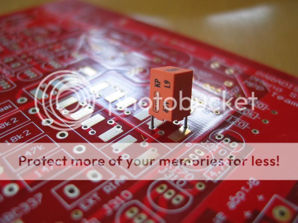
Yes clever board designed with that just in mind 😉
An externally hosted image should be here but it was not working when we last tested it.
These are the ones I have. Unfortunately, when I put them (all I have) on the Chinese tester, I got an "error device defect". Don't know whether that's the tester or the caps? 
As you see there are 2 types:
- marked emz (different logo than
posted earlier though), 100F (what value is that... 100pf?)
- marked s+m, 120F
KP is a film and foil polystyrene. The value ? Maye 100pF. 100nF is quite big so i asume it is pF.
Just my 2 pence advice
Be careful when soldering polystyrene don't like to much heath
Leave wires a bit long (space enough to hold wire with tweezers) and use the top pad as if they where delicate SMD components
Be careful when soldering polystyrene don't like to much heath
Leave wires a bit long (space enough to hold wire with tweezers) and use the top pad as if they where delicate SMD components
KP is a film and foil polystyrene.
KP is film and foil polypropylene; KS is polystyrene.
Peter
Btw;
they are real cuties from ancient eastern germany. !
Enjoy 😀
I hope, EMZ, a "eastern" bavarian company, doesn't read this....🙂
Peter
As you see there are 2 types:
- marked emz (different logo than
posted earlier though), 100F (what value is that... 100pf?)
- marked s+m, 120F
It's 100pF. EMZ bought the machines from Siemens to produce these caps. But as far as I know, they are no longer in capacitor business.
Peter
Eastern western Germany😀Quote:
Originally Posted by Benedetto
Btw;
they are real cuties from ancient eastern germany. !
Enjoy
I hope, EMZ, a "eastern" bavarian company, doesn't read this....
oncle_tom, you are right. Nevertheless this KPs are often sold as polystyrene or Styroflex, what is a trade name.
Does not seem to be right.
Does not seem to be right.
sorry, forgot to take that scope shot. But the output voltage was fluctuating +/-100mV with frequencies below 1Hz, and when I blew on the input stage transistors the voltage was moving quite a bit.... On my well-run-in Paradise those fluctuations were much smaller.
Hey Alfred what's up? Can you please refresh me here a bit? Got around to collect some missing parts today and stuffed some already on one board. What was the story with the 150K resistors around the opamp again? Am I supposed to use an order of magnitude lower so to surely get low DC offset or is it OK I start with or about the originally recommended? Thanx.
hi Salas, please just go ahead with the values as published. The output voltage will show low frequency fluctuations of ~100mVpp upon first turn on, and when the whole thing settles that voltage will come down.
This voltage is driven by the low frequency noise of the input dransistors, forming of the 6800uF elcaps, and thermal variations around the input stage. If it is too much, you could e.g. reduce the capacitor of the servo. Reducing the 150k resistors R43a/b is only necessary when there is too much (DC) offset in the amplifier, and the servo output (pin 6) is very high.
If the remainder of your system is not DC coupled, you should have no issue whatsoever.
hope that helps.....
Alright Alfred cheers for the clarifications, will start by the book. I just remembered having read something about it in the past here and thought I better confirm. Having to sort out some semis now I guess. Will use linear lab PSU and single channel first so to current limit for possible stuffing errors and to gather a reference set of measurements before adding its own PSU section.
As a matter of fact, using the stock 33.3nF in the riaa filter, the most correct value for the corresponding resistor would be 9550 ohm because 9550 x 0.0333 = 318uSanother pic of paradise 🙂. I did simple grounding and it is totally quiet. soundwise it startet with great dynamics but it was a little bright in my system with not very deep soundstage (a little metalised hüsker dü´sch). a post from RCruz encouraged me to play with just the 9.1k value of the RIAA and with about 9.3k to 9.6k i´ll find peace. Also the soudstage depth improved to be very good now. not shure if i had some oscillation. the improvement i felt in soundstage depth after installing the anti-osci-caps might have been a rather more psycolocical reason 😀
so yes, it is a fantastic sounding stage. thank you!!
stefan
![IMGDEAD]](/community/proxy.php?image=http%3A%2F%2F%5BIMGDEAD%5Dhttp%3A%2F%2Fi46.tinypic.com%2F2rgjtk4.jpg%5B%2FIMGDEAD%5D&hash=3992e59e868d143b72e56dd91241f4b2)
So your choice of 9k6 corroborates my calculations 🙂
Of course I would not stop there and somehow reduce the bass resistor and also increase the trebble cap to 11.4n but I am glad you like the aproximation.
- Home
- Source & Line
- Analogue Source
- Paradise Builders