Ok guys here I am again. I have several 6V 5AAcell NiMH battery packs that I use for model airplanes. My problem is discharging them. I have used a 6V 50mA light bulb and watched over them the correct amount of time but really want to build a simple circuit to cut the discharging off after 5.5V has been reached. Variable voltages and discharge rates would be great since I use several size and voltage packs but simple is the best. I have scoured the internet but nothing gives me what I need except expensive balancers. I did see one USB PC software ran balancer but it would not match my needs. Any ideas or links would be great especially a simple schematic. I keep thinking pots and LEDs for dicharge rates but how do I make it cut-off when 5.5V is reached? I could use a 7805 and a bulb but that would drop me to 5V and that is too low. I always get great feedback here and it is sooooo appreciated.😱
NiMH Battery Discharger - NiCad discharger Circuit
Could this be reworked and used?
What needs rework? There is a chart with component values for 3-10 cells. NiCad and NiMH are very similar in use and can often be swapped though you shouldn't mix them together. The main problem with actual batteries (multiple cells) is that the cells may not be matched and the weakest one will be die first and then reverse polarize as the other cells discharge through it - hence your 5 cell 5.5 Volt cutoff. Reverse polarity is BAD but running the cells down is good - self discharge while not in use.
G²
Maybe this could help... with some mods to fullfill your needs
http://bas.elitesecurity.org/discharger.html
http://bas.elitesecurity.org/discharger.html
nattawa: Does C9 polarity not matter? What would the V and A specifics be for D2? I am also very needy about how the Q1-A is actually put into the schematic. The datasheets I found on it are greek to me. I know I know over my head. Sorry. I do like this setup since I can trim it for different packs that I use though and the learning curve is great too.
Last edited:
The schematic I posted confuses me about a couple things. D2 = rosu? I am sorry but I have no clue. I don't understand the 3,9 V D1 in the table either. I am new to electronics and picking up on it quickly with a general understanding. I do not know what some of these in depth things equate to.
That circuit seems to be from an old Elektor magazine - the Romanian edition.
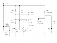
D2 is a red LED, and the D1 is a 3V9 zener diode. The table lists different zener and resistor values for various battery packs.
D2 is a red LED, and the D1 is a 3V9 zener diode. The table lists different zener and resistor values for various battery packs.
Are you sure what to expect from deep cycling NiMH batteries? Most sources say it doesn't help anything, and not doing it ensures the dreaded polarity reversal never happens. You'd likely improve cycle life without deep cycling.
C9 is a 0.1uF ceramic or film cap, has no polarity.Does C9 polarity not matter?
D2 can be any generic LED of any color of your choice, forward voltage drop is usually in the range of 1.7V - 2.5V. When working with 5.5V +B, the voltage across R6 is about 3.5V, the current through the LED would then be about 3.5mA.What would the V and A specifics be for D2?
Q1-A is a power MOSFET, its source goes to ground, drain is at R4, and its gate is driven by the U1-A output....how the Q1-A is actually put into the schematic...
Since the comparator LM139 is powered by the battery, its output goes between the ground level and the battery voltage. That works just fine with a 5-6V battery. However, if you use this circuit on different voltage batteries you need to take caution about a few things. The mosfet requires a minimum 4.5V across gate-source to turn on, the circuit may not work on batteries of a voltage lower than that. The mosfet can be damaged if 20V or higher voltage is applied across gate-source, you want to put in some protection when working with higher voltage batteries to limit the gate drive under, say 12V or 15V. The feedback resistor R3, together with R1, R2, and R7, give the comparator a hysteresis behavior. The hysteresis level is affected by the battery voltage as well. I would suggest a separate power supply, 9V or 12V, for the comparator and the voltage reference D1, if you want the circuit to suit various voltage batteries.
- Status
- Not open for further replies.
- Home
- Amplifiers
- Solid State
- NiMH battery discharger