So what about re-using my ribbon configuration?
Swopping the right magnet side of the left speaker with the left magnet side of the right speaker (I must be very careful if I do that):
Resulting b.n:
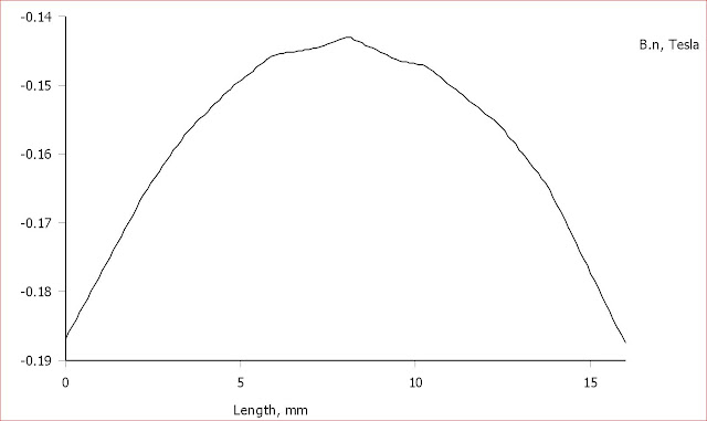
Not bad, it will have to be narrow driver though.
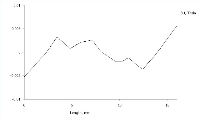
b.t looks good:
I must reverse the polarity of the right speaker of course.
Swopping the right magnet side of the left speaker with the left magnet side of the right speaker (I must be very careful if I do that):
Resulting b.n:
Not bad, it will have to be narrow driver though.
b.t looks good:
I must reverse the polarity of the right speaker of course.
Setups with weaker field in the center might be nice for diaphragms with smaller folds in the center. i.e. transitioning from a midtweet AMT to tweeter AMT in the center.
Setups with weaker field in the center might be nice for diaphragms with smaller folds in the center. i.e. transitioning from a midtweet AMT to tweeter AMT in the center.
Well that´s a great relief, so it can even be a desired setup.
But wouldn´t the level be lower for the tweeter in the middle then, having less air to compress/decompress?
EQ?
If the folds are the same all over, but the aluminium strips are narrower in the middle, the same force will be applied to all folds.
Last edited:
I was inspired by a Danish guy LGrau.
He has done some work with AMT too.From the bottom of this page and on:
HIFI4ALL Forum: Lyd laboratoriet
He tried first like your,s latest model.Didn't like resonanses from the system.
Bernt
He has done some work with AMT too.From the bottom of this page and on:
HIFI4ALL Forum: Lyd laboratoriet
He tried first like your,s latest model.Didn't like resonanses from the system.
Bernt
I am speculating, but I think that level matching could be achieved by finding the right combination of pleat width and depth. Deeper pleats have more mass to be moved so the stronger field will help at the edges. If there is more of a gap between pleats the air is loaded less efficiently. It looks like you could juggle all the variables if you had no day job. 😀
We can dream.
We can dream.
Well that´s a great relief, so it can even be a desired setup.
But wouldn´t the level be lower for the tweeter in the middle then, having less air to compress/decompress?
EQ?
If the folds are the same all over, but the aluminium strips are narrower in the middle, the same force will be applied to all folds.
Ok, so I made a test diaphragm from packing tape to see if it will make noise. 😀 Now I'll hunt for appropriate materials.
I noticed that there is mylar with alu on both sides - that might be pretty useful for etched traces with higher resistance without having to use the epsilon layout.
I noticed that there is mylar with alu on both sides - that might be pretty useful for etched traces with higher resistance without having to use the epsilon layout.
Looking at the ADAM diaphragm again (with the 2 traces), I wonder whether this is for better hinging as much as for resistance. It looks like one of the pictures in Heil's later patents about the hinging of the pleats.
It could be for better powerhandling.Longer"wire"=thicker "wire". And more weight.
I am making horns now ,and it looks good regarding FR.
Bernt
I am making horns now ,and it looks good regarding FR.
Bernt
Hi, I have been following this thread with interest and I came across this link from Beyma,
Beyma Professional Loudspeakers look for the document, AES_129_2010_SANFRANCISCO_Contributions_improvement_Pleated_Loudspeaker.pdf
I thought it would be of interest as I have not seen it before regarding the TPL150.
NBF
Beyma Professional Loudspeakers look for the document, AES_129_2010_SANFRANCISCO_Contributions_improvement_Pleated_Loudspeaker.pdf
I thought it would be of interest as I have not seen it before regarding the TPL150.
NBF
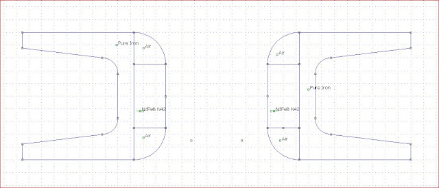
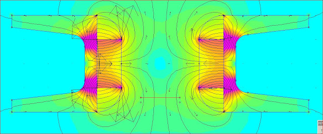
OB-1: Very interesting.
I did a simulation on something simular. The pole piece, the narrower section, is of course not solid in reality so the field is a little bit weaker and perhaps not so linear top to bottom.
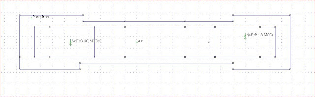

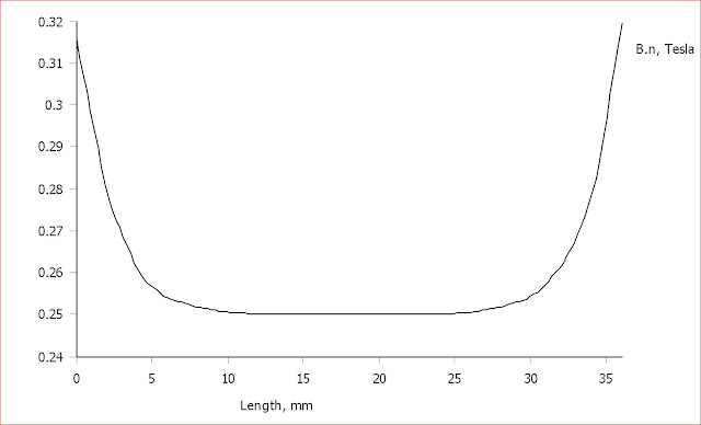
The b.t-field practically zero in the gap.
In a wider gap, the b.n-field breaks up and is not linear over the gap.
The stronger fields at the magnetes are useless because that´s were you probably need to have a supporting structure for the diaphragm anyway.
I´m thinking of having some sort of cassette for the diaphragm that you insert from the top.
I did a simulation on something simular. The pole piece, the narrower section, is of course not solid in reality so the field is a little bit weaker and perhaps not so linear top to bottom.
The b.t-field practically zero in the gap.
In a wider gap, the b.n-field breaks up and is not linear over the gap.
The stronger fields at the magnetes are useless because that´s were you probably need to have a supporting structure for the diaphragm anyway.
I´m thinking of having some sort of cassette for the diaphragm that you insert from the top.
Last edited:
Thanks for the Beyma link - interesting that they are doing all the mathematical modelling.
I'll probably have no pole piece and just neos right in front of the diaphragm.
On the way home yesterday I noticed a rescue blanket and bought it - 12 um aluminized mylar. One thing that I'm going to try is electroplating it to reduce resistivity and then etching that. I'm hoping to avoid glues.
I checked again and ADAM do say they use purely physical heat pressing of the traces. Maybe this is doable with kapton, but I don't think mylar can handle it.
What size of Neos do you have in mind?I'll probably have no pole piece and just neos right in front of the diaphragm.
I think that the 30 mm ones look about right and they aren't so expensive. I'm buying some as a prize when I hand in my dissertation. I don't want to go wider than 1 inch for the exposed part of my diaphragm.
It seems that plating onto Alu is difficult - I guess that I will glue instead. Need a nice choice for glue though, that's cheaper than buying kapton tape. 😀 I saw 50 mm kapton tape for about 6 EUR on ebay. I'll buy it sooner or later I guess, but first I'll try with the 12 mylar.
It seems that plating onto Alu is difficult - I guess that I will glue instead. Need a nice choice for glue though, that's cheaper than buying kapton tape. 😀 I saw 50 mm kapton tape for about 6 EUR on ebay. I'll buy it sooner or later I guess, but first I'll try with the 12 mylar.
So you will have Neos and gaps interlaced? Could you provide a simple sketch?
40x5x5 Neos would be super, having them with 10 mm gaps inbetween.
I´ve used 3M's Spray Mount or Scotch 77 spray for gluing alu-strips on mylar that still holds after two years of heavy use.
40x5x5 Neos would be super, having them with 10 mm gaps inbetween.
I´ve used 3M's Spray Mount or Scotch 77 spray for gluing alu-strips on mylar that still holds after two years of heavy use.
![URL]](/community/proxy.php?image=http%3A%2F%2F%5BURL%3Dhttp%3A%2F%2Fimg705.imageshack.us%2Fi%2Famtstdplandraw.jpg%2F%5D%5BIMGDEAD%5Dhttp%3A%2F%2Fimg705.imageshack.us%2Fimg705%2F5696%2Famtstdplandraw.jpg%5B%2FIMGDEAD%5D%5B%2FURL%5D&hash=8c3ee7d0757b4d6d23c848c8287adce4)
Dont use iron at the ends´,it shortens magn.field.
![URL]](/community/proxy.php?image=http%3A%2F%2F%5BURL%3Dhttp%3A%2F%2Fimg94.imageshack.us%2Fi%2Famtstdplanans.jpg%2F%5D%5BIMGDEAD%5Dhttp%3A%2F%2Fimg94.imageshack.us%2Fimg94%2F6721%2Famtstdplanans.jpg%5B%2FIMGDEAD%5D%5B%2FURL%5D&hash=e9ef8df7e73a30d779692ad0bdfdbf2a)
![URL]](/community/proxy.php?image=http%3A%2F%2F%5BURL%3Dhttp%3A%2F%2Fimg585.imageshack.us%2Fi%2Famtstdplanfieldstrength.jpg%2F%5D%5BIMGDEAD%5Dhttp%3A%2F%2Fimg585.imageshack.us%2Fimg585%2F5553%2Famtstdplanfieldstrength.jpg%5B%2FIMGDEAD%5D%5B%2FURL%5D&hash=541c2b9cdebf20f27a6877857cdcf111)
This is made with 5x10 neodymn. 5mm.gap.Iron 2,5mm.Might be 4mm. with holes.
Bernt
Yes, you are right. I did simulation for such a configuration but didn´t have avy pics to upload.
Having Neos as "pole pieces" doesn´t seem to a good configuration though.
Having Neos as "pole pieces" doesn´t seem to a good configuration though.
Sorry, but I'm too busy chasing a deadline to sketch something up - I'm imagining something very simple though, just planks of neos across the front with pole pieces only if I really need them.
Will be building as soon as my studies are done.
Will be building as soon as my studies are done.
Hi SEdwards
Here is a tread showing a diy amt "motor".There are measurements too.
http://www.avsforum.com/t/1364670/an-information-roundup-for-larger-amts
Bernt
Here is a tread showing a diy amt "motor".There are measurements too.
http://www.avsforum.com/t/1364670/an-information-roundup-for-larger-amts
Bernt
Last edited:
- Status
- Not open for further replies.
- Home
- Loudspeakers
- Planars & Exotics
- Diy AMT