car lamps 55w for headlights and 21w for the back55 and 21 W don't exist as values for 'old type' lightbulbs
I know 25 and 60 W ratings ! So, are you sure that you are referring to
the classic lightbulbs, and not the electronic ones ?
Same for the power supply
RE: I blew those crappy speakers from the moment I see

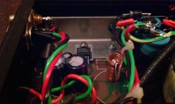
That was just for a test at 12v how many times do i have to say itYour heatsink pictures is inadequate; it has to be much more substantial or the chip will thermally runaway or fail! Start with something 70x90x50mm long fins and keep supply rails as low as possible for desired output power.
powered from +- 12v
If i connect a wire from ground to in the weird noises stop and the speaker just goes down with no weird noises
May this be because i havent used the 1m resistor on input or that i used 22k instead of 20k from out to inverting input
If i connect a wire from ground to in the weird noises stop and the speaker just goes down with no weird noises
May this be because i havent used the 1m resistor on input or that i used 22k instead of 20k from out to inverting input
Attachments
![DSCF2877[1].jpg](/community/data/attachments/295/295302-9c68c6622fac1e40ba42dbee0bb326cc.jpg)
Last edited:
" That was just for a test at 12v how many times do i have to say it "
You don't mention the 12V untill someone appears to guess it about 1/3 of the way through the posts, or have you edited them, I see no previous mention of the actual rail value?
Even at lowish +/- 12V split supply you will need Proper heatsinking regardless, it takes too much quiescent power to dissipate without heatsink!
Last edited:
It was just for couple second long test" That was just for a test at 12v how many times do i have to say it "
You don't mention the 12V untill someone appears to guess it about 1/3 of the way through the posts, or have you edited them, I see no previous mention of the actual rail value?
Even at lowish +/- 12V split supply you will need Proper heatsinking regardless, it takes too much quiescent power to dissipate without heatsink!
I did build a pair of these LM1875 up on some old maplin pcbs I just happened to have lying around some years back.
Using a 30VA 18-0-18V transformer managed to cram complete circuit and mains power supply all into a Hammond extruded case and made 2 off monoblocks as such.
I can send pics if interested.
Using a 30VA 18-0-18V transformer managed to cram complete circuit and mains power supply all into a Hammond extruded case and made 2 off monoblocks as such.
I can send pics if interested.
I would like some pics
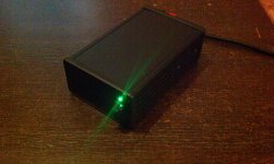
1. Front view of my LM1875 laboratory amplifier. designed really for listening tests it features bootstrapped input to give 1M ohm input impedance, so it can be used with high output impedance valve preamplifiers!
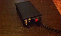
2. Rear View of unit there are two phono sockets connected together internally and go to the input on the amplifier pcb. This allows any source connected to be routed on to another place if necessary. The Silver 3 pin plug is a future uprade to allow a regulated power supply upgrade. the speaker terminals are cheapo sprung ones but could also be gold plated 4mm banana sockets if preferred. The mains lead is a 2M length of molded cable/mains plug permanently wired in to the unit.
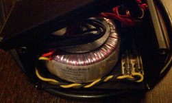
3. Front view with front lifted away, transformer and secondary fuses (to the right) visible. these fuses are wired before the bridge rectifier (small black block type - not visible - but just behind the fuses)
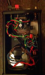
4. Top view a common mode HF choke comes from the rectifier to the reservoir capacitors 4700uF 35V then go on to the board supply connections. The two fat diodes are the regulated supply upgrade path. A diamond earth keeps charging currents out of the amplifier ground. The orange capacitor has a 47R resistor (value is arbitrary, just a few 10s of ohms will do!) in parralell and these connect oV to the chassis which is of course earthed.
5. Closeup of the Maplin PCB LM1875. to repeat this project any suitable PCB can be used and the following devices and their PCBs are interchangeable (taking care not to exceed max supply rails for each device and any electrolytic capacitors!): LM1875, TDA2030, TDA2040, TDA2050.
The outer case is extruded aluminium and has sufficient surface area to act as a heatsink. The LM1875 in standing or operation raises the temperature and the box runs slightly warm to the touch which is to be expected. Heavy loads 4 ohms etc cause more heating but I've not had these shut down on me yet (4 years and counting). The enclosure is available from outlets supplying Hammond enclosures and should be approx. UK£10.00
That's about it. Oh ,and they sound great. I've still got to get matching boxes for the regulated power supplies but Maplin (UK) have stopped stocking them so I'm going to have to do a MOQ order from Farnell who are cheaper in the long run anyway!
Attachments
Last edited:
I tested this amp with an steper motor as input,when i turn it slowly i can quietly her it in the speaker,if i turn it just alittle faster is very loud,is that normal,after a certain input level the amp fully kicks in,because the input sensitivity not amplifing too quiet signals
I know that but just a tiny bit faster makes a very large diference,but i think thats normal, anyways is it now safe to plug into a computerThe faster you turn a motor the more efficient it gets, so yes, thats what I'd expect....
Like the kind of stuff i dont have?,someone from here needs to post a simple oscilator scematic using any pnp,npn transistorsIf you're not sure if it's OK you might try plugging it into something somewhat cheaper than your computer, e.g. old walkman from headphone out will do!!
- Status
- This old topic is closed. If you want to reopen this topic, contact a moderator using the "Report Post" button.
- Home
- Amplifiers
- Chip Amps
- lm1875 fizzing away probelm