First a brief history:
I started to build a 3 band Equalizer using NE5532 as per this website. 3 band EQ
First I tested the second part of the circuit on a breadboard and it worked as expected. ( attachment: graphic eq on bread board.jpg )
Then I made a quick PCB and built it.
Upon first power up it worked nicely but I found 2 problems
1. after some 10 seconds the sound started to spark
2. and gain reduced.
I touched my fingers at the input and it became normal again for another 10 seconds.
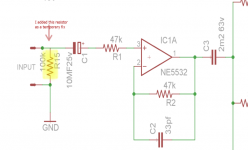
I added a 100k bypass Resistor infront of the 10uf/63v Electrolytic cap like this below in the input and the problem was solved! (Kindly see the attachment EQ FIX 1.png )
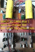
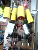
After some days I replaced the electrolytic input caps with a bigger nonpolar 10UF/100v caps. I found the sound was improved . I was happy. But after some 5 minutes the previous problem reappeared. i.e gain reduced and sparking noise.
I monitored the voltage ... +-15v okay, no over heating of the ICs, No pcb foil line is damaged. I tried my best to solve that but alas...
As a last resort I had to use the electrolytic caps again with the 100k biasing resistor.
Could please help me fix this problem so that I can use the bigger caps instead of the el-caps?
eq question how to solve .jpg
Thank you,
Best regards,
Som.
I started to build a 3 band Equalizer using NE5532 as per this website. 3 band EQ
First I tested the second part of the circuit on a breadboard and it worked as expected. ( attachment: graphic eq on bread board.jpg )
Then I made a quick PCB and built it.
Upon first power up it worked nicely but I found 2 problems
1. after some 10 seconds the sound started to spark
2. and gain reduced.
I touched my fingers at the input and it became normal again for another 10 seconds.
I added a 100k bypass Resistor infront of the 10uf/63v Electrolytic cap like this below in the input and the problem was solved! (Kindly see the attachment EQ FIX 1.png )
After some days I replaced the electrolytic input caps with a bigger nonpolar 10UF/100v caps. I found the sound was improved . I was happy. But after some 5 minutes the previous problem reappeared. i.e gain reduced and sparking noise.
I monitored the voltage ... +-15v okay, no over heating of the ICs, No pcb foil line is damaged. I tried my best to solve that but alas...
As a last resort I had to use the electrolytic caps again with the 100k biasing resistor.
Could please help me fix this problem so that I can use the bigger caps instead of the el-caps?
eq question how to solve .jpg
Thank you,
Best regards,
Som.
Attachments

Last edited:
sounds like an earthing issue to me, possibly a ground loop issue.
Reason for thinking this is that you touched the input with your fingers and that fixed it.
Get some perfboard and put the project onto that.
Reason for thinking this is that you touched the input with your fingers and that fixed it.
Get some perfboard and put the project onto that.
The positive input to the 5532 needs a resistance to earth to give it a reference. Move the top of R15 to the junction of C1 & R1.
Thank you freax.
I am lost as the el-caps are working perfectly with the 100k resistor but the bigger nonpolar ones ( which are dramatically improving the performance) fail.
I checked the ground continuity too. No problem there .
🙁
I am lost as the el-caps are working perfectly with the 100k resistor but the bigger nonpolar ones ( which are dramatically improving the performance) fail.
I checked the ground continuity too. No problem there .
🙁
The positive input to the 5532 needs a resistance to earth to give it a reference. Move the top of R15 to the junction of C1 & R1.
Thank you Bone !
Is the gain of that buffer stage 2? If yes can I use a 47k instead of that 100k ?
That was the second thing I did Freax It worked okay . Although the buffer stage was not there. Its the buffer stage that's the culprit here.......
Get some perfboard and put the project onto that.
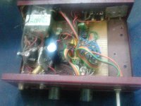
Here is the pic
Attachments
Last edited:
Your schematic does not correspond to original.
Original shows an inverting opamp config.
You enter into + input. when this one should be grounded.
Original shows an inverting opamp config.
You enter into + input. when this one should be grounded.
Your schematic does not correspond to original.
Original shows an inverting opamp config.
You enter into + input. when this one should be grounded.
OUCH!! A "BIG FALE" for me !!!
Thank you so much bobo for pointing out that!
Re-designing the PCB now!
Sigh!
Last edited:
Fixed the prototype. No more sparking or gradual gain reduction now.
Improvement: Noise is minimized to a great extent.
But the stereo image/ sound stage is reduced. weird. Earlier it was better.
Could you please suggest what can be done to increase Stereo image ?
Regards,
Som.
Improvement: Noise is minimized to a great extent.
But the stereo image/ sound stage is reduced. weird. Earlier it was better.
Could you please suggest what can be done to increase Stereo image ?
Regards,
Som.
Attachments
Problem solved! One of the pots ( midrange 100k ) had a dry solder joint.
All fixed now! Sound stage restored again !
Working great now! Thank you all!
If any newcomer, hobbyist ,like me, wants a quick, simple yet very effective Equalizer solution and add it to your DIY amp, please go ahead and give it a try, you will be surprised to see its performance. 🙂
Regards,
Som
All fixed now! Sound stage restored again !
Working great now! Thank you all!
If any newcomer, hobbyist ,like me, wants a quick, simple yet very effective Equalizer solution and add it to your DIY amp, please go ahead and give it a try, you will be surprised to see its performance. 🙂
Regards,
Som
Last edited:
I am lost as the el-caps are working perfectly with the 100k resistor but the bigger nonpolar ones ( which are dramatically improving the performance) fail.
The electrolytic has just enough leakage current such that it allows a DC path from the + input to the 47k resistor, the e-cap, and 100k resistor to ground. The film cap has very little (if at all) leakage current that's why the circuit no longer works with it.
The electrolytic has just enough leakage current such that it allows a DC path from the + input to the 47k resistor, the e-cap, and 100k resistor to ground. The film cap has very little (if at all) leakage current that's why the circuit no longer works with it.
Thank you so much for your valuable input djQUAN.
I fixed the prototype as per the original circuit and everything is really nice sounding , with hardly perceptible noise even at the highest volume with the magic of NE5532.
Regards,
Som
Last edited:
I have seen some manufacturers use electrolytic caps in graphic equalizer and audio amplifier kits in the signal path.
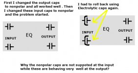
Just a question , if nonpolar caps are performing so nicely both at the signal input and output stage why the designer used electrolytic caps ? ( ref: post 1)
Is this a mere cost factor?
Just a question , if nonpolar caps are performing so nicely both at the signal input and output stage why the designer used electrolytic caps ? ( ref: post 1)
Is this a mere cost factor?
LOL 😀
I must be careful in future before I spend a fortune again , after this post.😛
I must be careful in future before I spend a fortune again , after this post.😛
Last edited:
I found a new problem with the nonpolar caps I changed.
When the audio signal is fed from the output of the soundcard of the PC, it works very nicely and perfectly at a stretch without any problem.
But, when I connect cel phone, or other media player, the earlier low gain, sparking noise etc are reappearing again after some 2 minutes.
Could anyone kindly suggest how to fix that?
Thank you.
is the headphone output from the cell phone turned up too loud?
It could also be picking up transmissions from the cellphone... unavoidable unless you take extreme measures to shield the input.
It could also be picking up transmissions from the cellphone... unavoidable unless you take extreme measures to shield the input.
Thank you so much freax for your response.
The output from the cell phone is not high. There was no overloading.
And the phone was connected in flight mode.
The output from the cell phone is not high. There was no overloading.
And the phone was connected in flight mode.
is the headphone output from the cell phone turned up too loud?
Freax, I also checked with two other media players with the line out option.
But same problem.
With electrolytic caps everything is working but not with nonpolar input caps. ( and electrolytic caps are used in the original circuit ).
- Status
- Not open for further replies.
- Home
- Source & Line
- Analog Line Level
- GHOST in 3 band graphic equalizer!! SOS!