I'm not sure whether the circuits I've been able to find are exactly the same as yours and what the differences are between the 8000P and and 8000.
I'll put some simple tests together though to see if we can see whats going on.
I'll put some simple tests together though to see if we can see whats going on.
If any steps here seem odd or wrong its because the circuit I have will be slightly different but lets see where we get 🙂
Step 1. for safety and to prevent mishaps has to be to wire the bulb tester in. With the amp on the bulb should only dimly glow (drawing little current).
Step 2. The 0.22 ohm 3 legged resistors (the outer pair of resistors not the middle one). Measure the DC voltage on the middle leg of each. That should be the supply voltage. One should read say plus 40 or 50 volts and the other minus 40 or 50. I'm not sure what the exact voltage is but it will be in that region. The plus and minus rails should mirroe each other.
Step 3. Measure the DC voltage on the two outer legs of each of these 0.22 ohms. It should be the same as the middle.
Step 4. Measure the DC voltage on the middle leg of the CENTRE resistor. Is it 0.22 ohm like the others ? It should be zero volts DC.
Step 5. Measure the DC volts on each of the outer legs of this same resistor. It should be essentially zero to within a few millivolts.
There the first basic steps to get an idea of whats going on.
Compare your readings one channel to other too.
The bulb tester is a 60 or 100 watt mains filament lamp in series with the live mains to the amp. It limits current in the event of a fault.
.
If any steps here seem odd or wrong its because the circuit I have will be slightly different but lets see where we get 🙂
Step 1. for safety and to prevent mishaps has to be to wire the bulb tester in. With the amp on the bulb should only dimly glow (drawing little current).
.
Morning, and thank you for those first steps.. 🙂
Sorry for sounding thick, I'm a little unsure what is required with step 1, where about's should I connect the Mains filament lamp to?
Another question, is there any where else in the UK I could buy a replacement OMRON G2R-1 DC 24V 5PIN Power Relay & pedestal, I have had a look at RS, nothing seems to fit the bill.
OMRON G2R-1 DC 24V 5PIN Power Relay & pedestal | eBay
The bulb is an ordinary household 60 or 100 watt filament bulb. It goes in series with the live wire to the amplifier.
If the amplifier actually powers up OK now (as it is) with no signs of distress then you can proceed without the bilb tester for now. Just be careful with the meter probes... no slips or shorts as it could be a disaster.
Edit... I'd have to look for the relays
If the amplifier actually powers up OK now (as it is) with no signs of distress then you can proceed without the bilb tester for now. Just be careful with the meter probes... no slips or shorts as it could be a disaster.
Edit... I'd have to look for the relays
Step 1. for safety and to prevent mishaps has to be to wire the bulb tester in. With the amp on the bulb should only dimly glow (drawing little current).
Step 2. The 0.22 ohm 3 legged resistors (the outer pair of resistors not the middle one). Measure the DC voltage on the middle leg of each. That should be the supply voltage. One should read say plus 40 or 50 volts and the other minus 40 or 50. I'm not sure what the exact voltage is but it will be in that region. The plus and minus rails should mirroe each other.
Step 3. Measure the DC voltage on the two outer legs of each of these 0.22 ohms. It should be the same as the middle.
Step 4. Measure the DC voltage on the middle leg of the CENTRE resistor. Is it 0.22 ohm like the others ? It should be zero volts DC.
Step 5. Measure the DC volts on each of the outer legs of this same resistor. It should be essentially zero to within a few millivolts.
.
Step 2 -64.9 + 64.9 on both channels
Step 3 is the same
Step 4 Right 0 VDC, Left 16 VDC
Step 5 same as above.
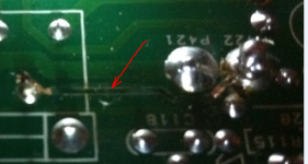
So all checks OK except for left channel Center resistor, this is the on the amp side with the relay out of circuit and the faulty track wire.
Step 2. confirms the supply as -/+ 65 volts. Thats fine.
Step 3. OK for now.
Step 4 and 5. That 16 volts is the problem.
Where next 🙂
Have you repaired the burnt out track with wire ?
Depending on the PCB layout it could be important that the print is intact and all components that are meant to be connected are. That 16 volts while obviously incorrect is an "odd" voltage to find with a failed output stage. Usually the output swings hard to one or other rail.
After repairing the print I would advise the bulb tester, just be safe and sure in case there is a short somewhere. (I find it easiest to solder wires to the bulb and then tag the other ends of the wires across the mains fuse in the amp. Then remove the fuse of course so the bulb can do its job. Keep the bulb and any bare leads insulated for your safety)
If the print wasn't repaired then repeat the above checks and reconfirm that there is still 16 volts offset or whether it has altered.
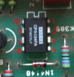
The circuit I am looking at has an opamp in each channel (8 legged IC). Measure the DC voltage on pin 7 and pin 4. There should be + 12 on pin 7 and - 12 volt on pin 4.
Do you have the circuit ? Its widely available on the web although all versions seem to be the same copy.
Step 3. OK for now.
Step 4 and 5. That 16 volts is the problem.
Where next 🙂
Have you repaired the burnt out track with wire ?
Depending on the PCB layout it could be important that the print is intact and all components that are meant to be connected are. That 16 volts while obviously incorrect is an "odd" voltage to find with a failed output stage. Usually the output swings hard to one or other rail.
After repairing the print I would advise the bulb tester, just be safe and sure in case there is a short somewhere. (I find it easiest to solder wires to the bulb and then tag the other ends of the wires across the mains fuse in the amp. Then remove the fuse of course so the bulb can do its job. Keep the bulb and any bare leads insulated for your safety)
If the print wasn't repaired then repeat the above checks and reconfirm that there is still 16 volts offset or whether it has altered.
The circuit I am looking at has an opamp in each channel (8 legged IC). Measure the DC voltage on pin 7 and pin 4. There should be + 12 on pin 7 and - 12 volt on pin 4.
Do you have the circuit ? Its widely available on the web although all versions seem to be the same copy.
No I hadn't repaired the track, I will now 😱
Funnily enough, I can't see a fuse in my 8000p??
I can see the opamp.
Yep, I have a circuit diagram off the web. 🙂
Funnily enough, I can't see a fuse in my 8000p??
I can see the opamp.
Yep, I have a circuit diagram off the web. 🙂
You can always (and usual safety precautions apply) remove the fuse from the plug top and solder the wires from the bulb directly across the fuse holder in the plug.
What I'm getting at the with print to the relay (if it is "too" and not "from") is that the feedback network is actually connected. That is that points "d" and "e" connect to the main amp output which is that central line marked "c" and "f".
For testing you can always link the relay out... we're not going to be connecting speakers for a while yet.
You can also usefully check all the low value resistors particularly the two 22 ohms in each supply and the 100, 10, 56 and 330 ohm resistors all in the middle area of the circuit.
Once the amp can be powered up (knowing the feedback network is in place and connected) then careful voltage checks on the outputs and drivers should reveal the problem. All the evidence is there 🙂
that burnt out track is connected to COM (the common connection of the double throw switch).This burn't out track is feed off one of the 'removed relay' pins, will I have to wait for my new relays before I can carry out those checks again?
That almost certainly indicates excessive output current. That in turn indicates user abusing the amplifier.
that burnt out track is connected to COM (the common connection of the double throw switch).
That almost certainly indicates excessive output current. That in turn indicates user abusing the amplifier.
You mean the relay Andrew ? I wish I had the full correct circuit to see how it all connects up.
That print looks thin gauge for the total output of such an amplifier.
deliberate fuse?
The 8000p has a quite different sch, but I don't have a copy. It too went through a lot of incarnations with different component values. And again when it went TAG.
The 8000p has a quite different sch, but I don't have a copy. It too went through a lot of incarnations with different component values. And again when it went TAG.
OK, lamp up and running.
Linked across relay. Tested the bad resistor, this time read 7 VDC across all terminals.
Linked across relay. Tested the bad resistor, this time read 7 VDC across all terminals.
that burnt out track is connected to COM (the common connection of the double throw switch).
That almost certainly indicates excessive output current. That in turn indicates user abusing the amplifier.
I am guilty of that, I should have known better. Had some fellow AV friends round. 😱
OK, lamp up and running.
Linked across relay. Tested the bad resistor, this time read 7 VDC across all terminals.
And the lamp is dim or out yes ? If its bright there is a problem.
The -/+65 volt rails should be up but will be a little lower due to the bulb.
Are the suppies correct on that opamp ?
Lets be practical... in the absense of the correct circuit we're going to have to fall back on what has happened and what the consequencies are of that. By your own admission it had a good workout 🙂
Amplifier faults like this are normally confined to the output and driver stages as these are what suffer when excess current is drawn.
If you look at the circuit you'll see there are four (two pairs) of output transistors. Feeding these transistors are two more pairs of transistors, the drivers and "pre drivers". Although your circuit seems slightly different it will have these components.
So general things for you to check.
The transistors can only easily be checked for leakage when at least two of the legs are isolated... in other words out of circuit. There should be infinite resistance between the collector and emitter when your DVM is on a high ohms range (and the leads correct polarity... red lead to collector and black to emitter for NPN and vice versa for PNP)
So thats an essential check on ALL the output and driver transistors.
Also check all the low value resistors in that part of the circuit. Anything under say 1K. If they read the correct value in circuit then thats usually good enough... if they don't then you have to lift one end to bring them out of circuit.
Also measuring the DC voltage ACROSS the base and emitter junction of the transistors can be very revealing indeed for locating faults. They should all be in the 0.7 volt region.
I can say this from buying a used audio labs 8000a made in 1999. It is a very good unit but, I had to replace the tone caps. They were making the right channel buzz in and out and then it stopped working for about 10 minutes. Looking aound I noticed some of the circuit board in parts were it was soldered was a red color and the others silver colored. I still have problems but, not so bad.I don't use the tone switch anymore. I really don't use this little gem due to the fact of audiolabs never returning my e-mails? I would have no Idea were to get parts? Also I really need someone to go thru it and make sure its working okay so I don't fry it? This is the my first real big buy and go figure I am left burned 🙁. Jm
Last edited:
The -/+65 volt rails should be up but will be a little lower due to the bulb.
Lets be practical... in the absense of the correct circuit we're going to have to fall back on what has happened and what the consequencies are of that. By your own admission it had a good workout 🙂
So general things for you to check.
The transistors can only easily be checked for leakage when at least two of the legs are isolated... in other words out of circuit. There should be infinite resistance between the collector and emitter when your DVM is on a high ohms range (and the leads correct polarity... red lead to collector and black to emitter for NPN and vice versa for PNP)
So thats an essential check on ALL the output and driver transistors.
Also check all the low value resistors in that part of the circuit. Anything under say 1K. If they read the correct value in circuit then thats usually good enough... if they don't then you have to lift one end to bring them out of circuit.
Also measuring the DC voltage ACROSS the base and emitter junction of the transistors can be very revealing indeed for locating faults. They should all be in the 0.7 volt region.
Reading 54 VDC across the resistors now, and 7 VDC on the Left channel middle resistor.
Wow, that's all starting to get a little heavy now. This could take some time 🙄
- Status
- Not open for further replies.
- Home
- Amplifiers
- Solid State
- Audiolab 8000p stopped working.