Dipol- und Kardioid Subwoofer
Maybe some in here are interested in dipole subwoofers too.
I post the configurations from A) to D) without practical building plans.
Maybe a discussion about applicability , pro's and cons will develop.
Cheers
Maybe some in here are interested in dipole subwoofers too.
I post the configurations from A) to D) without practical building plans.
Maybe a discussion about applicability , pro's and cons will develop.
Cheers
Last edited:
I don't see much of anything that is new or very interesting on that web page... the author is mostly taking two of the same thing to create two separated sources. I am skeptical of any claims of these being "better" that could not be achieved with existing dipole systems...
For subwoofer use, double bandpass dipole might be worth trying, but because of the increased rolloff from the bandpass loading and likely reduced efficiency or larger size compared to a W-frame type dipole I don't think that it offers any advantages.
-Charlie
For subwoofer use, double bandpass dipole might be worth trying, but because of the increased rolloff from the bandpass loading and likely reduced efficiency or larger size compared to a W-frame type dipole I don't think that it offers any advantages.
-Charlie
Sure, the bandpass dipole may not be the most compact design.
But (1) it allows fairly large dipole path length.
Doubling the path length will usually halve the volume
displacement needed from the driver for a given SPL.
Path lenghts of say 1m are easily realised using that approach.
Usual H- or W frames typically have smaller dipole separation and
have to account for unwanted lambda/4 resonances possibly occuring
at the upper end of the passband, when separation is stretched too
far.
(2) If the tuning frequency is aligned properly for excitation of
the lowest room modes (longest room axis excited ) of "usual" living
rooms and not too low, the excursion of the driver is significantly
reduced at the lower end due to mechanical impedance of the two
vented chambers. A feature which usual "dipole frames" do not have.
Of course an electronic highpass filter would be desirable with the
"dipole bandpass cabinet" approach to make use of the dynamic headroom
fully and not waste cone excursion below the cabinet's tuning frequency
and/or lowest room modes.
(3) The falling slope (with rising freuency) in the range (far) above fb
using the bandpass approach is not a problem since usual baffled or framed
dipoles have a 6db/octave rise instead ...
That dipole rise is compensated by the bandpass cabinet.
In fact in the range far above fb it is overcompensated, because the
sound pressure from either port would fall with 12db/octave slope.
But with the cabinet aligned to sufficient bandwidth around fb, that
effect does not show up in real room situations and the subwoofer can
cover 1.5 ... 2 octaves easily.
(4) Harmonics from the driver are filtered acoustically by the
cabinet, a feature which usual frames do not have.
Of course the ports have to be aligned for low noise, to not
introduce THD this way ...
You would be right in stating, that in a "usual W,N or H frame"
- or even the "Stepped M-Frame" i proposed - you can easily install by far
more displacement volume from the driver side using comparable cabinet
size by simply installing more and larger drivers.
But that kind of frames typically need more then four times the volume
displacement (at driver's side) ... if you compare at the bandpass' tuning
frequency (due to combined effects of higher dipole separation AND
mechanical impedance of the cabinet).
So i would say if you install >4x the displaced volume in a typical W-Frame
you can have more headroom than in the bandpass case and you are usually more
compact.
But you will (usually) spend a multiple of the money too ... for the drivers.
So in the end the dipole bandpass may be seen as "budget design", allowing
to make a high quality dipole sub with fairly low displacement volume available
from the driver and allowing simple crossovers with say 12db/octave even for
mono subwoofer applications. Those can even be realized as PLLXO.
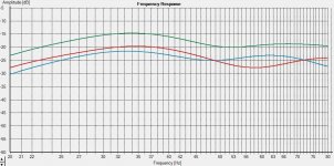
1st pic:
Attached Frequency response is at different positions in the room,
"left" (red) and "right" (blue), sum is calculated in Holmimpulse.
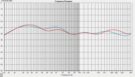
2nd pic: Similar settuing but without sum and range up to 300Hz.
But (1) it allows fairly large dipole path length.
Doubling the path length will usually halve the volume
displacement needed from the driver for a given SPL.
Path lenghts of say 1m are easily realised using that approach.
Usual H- or W frames typically have smaller dipole separation and
have to account for unwanted lambda/4 resonances possibly occuring
at the upper end of the passband, when separation is stretched too
far.
(2) If the tuning frequency is aligned properly for excitation of
the lowest room modes (longest room axis excited ) of "usual" living
rooms and not too low, the excursion of the driver is significantly
reduced at the lower end due to mechanical impedance of the two
vented chambers. A feature which usual "dipole frames" do not have.
Of course an electronic highpass filter would be desirable with the
"dipole bandpass cabinet" approach to make use of the dynamic headroom
fully and not waste cone excursion below the cabinet's tuning frequency
and/or lowest room modes.
(3) The falling slope (with rising freuency) in the range (far) above fb
using the bandpass approach is not a problem since usual baffled or framed
dipoles have a 6db/octave rise instead ...
That dipole rise is compensated by the bandpass cabinet.
In fact in the range far above fb it is overcompensated, because the
sound pressure from either port would fall with 12db/octave slope.
But with the cabinet aligned to sufficient bandwidth around fb, that
effect does not show up in real room situations and the subwoofer can
cover 1.5 ... 2 octaves easily.
(4) Harmonics from the driver are filtered acoustically by the
cabinet, a feature which usual frames do not have.
Of course the ports have to be aligned for low noise, to not
introduce THD this way ...
You would be right in stating, that in a "usual W,N or H frame"
- or even the "Stepped M-Frame" i proposed - you can easily install by far
more displacement volume from the driver side using comparable cabinet
size by simply installing more and larger drivers.
But that kind of frames typically need more then four times the volume
displacement (at driver's side) ... if you compare at the bandpass' tuning
frequency (due to combined effects of higher dipole separation AND
mechanical impedance of the cabinet).
So i would say if you install >4x the displaced volume in a typical W-Frame
you can have more headroom than in the bandpass case and you are usually more
compact.
But you will (usually) spend a multiple of the money too ... for the drivers.
So in the end the dipole bandpass may be seen as "budget design", allowing
to make a high quality dipole sub with fairly low displacement volume available
from the driver and allowing simple crossovers with say 12db/octave even for
mono subwoofer applications. Those can even be realized as PLLXO.
1st pic:
Attached Frequency response is at different positions in the room,
"left" (red) and "right" (blue), sum is calculated in Holmimpulse.
2nd pic: Similar settuing but without sum and range up to 300Hz.
Attachments
Last edited:
btw. i would not recommend using this kind of subwoofer say > 120Hz,
but as one can see, there is little to be seen from the "bandpass"
charcteristics of that cabinet in a usual inroom situation.
Measurements are without any crossovers/filters.
but as one can see, there is little to be seen from the "bandpass"
charcteristics of that cabinet in a usual inroom situation.
Measurements are without any crossovers/filters.
Last edited:
Now explain how dipole is supposed to work when at bass frequencies, a single driver is basically omni-directional.
at
Dipol- und Kardioid Subwoofer
in Picture B) there is an effective dipole pathlength
between the two ports at the outside of the cabinet.
That dipol pathlength depends on cabinet dimensions,
but will typically be >80cm.
Since both ports act in antiphase, dipole radiation is
kind of inevitable ...
Front and rear of the driver act on separate
chambers.
btw. this type of cabinet is not "just an idea", the
measurements posted show the performance of the
"real thing" in a "real listening room".
So no "does it work" question concerning the "bandpass
dipole" approach here ...
Last edited:
Now explain how dipole is supposed to work when at bass frequencies, a single driver is basically omni-directional.
Unfortunately this was exactly what i tried to do ...
by explaining this arrangement not being a single
driver from the radiation point of view.
This sheet
www.linkwitzlab.com/spl_max1.xls
summarizes the relationship between displaced volume
needed for a certain SPL depending from dipole pathlength
and frequency.
(However excitation of modes in a real listening room
is not accounted for.)
If i misunderstood your question, maybe you could refine it.
Otherwise i assume your contribution
Sigh....
was just intended to spread bad mood ...
Last edited:

- Status
- Not open for further replies.
- Home
- Loudspeakers
- Subwoofers
- Some new types of dipole subwoofers