well if you don't like x-formers what are your thoughts on wide band opto isolators.
They are great for digital signals, when their linearities don't matter. But I did not say that I don't like transformers. I don't like their costs. And mass that they add. And frequency limitations. And distortions they add. But I prefer to use them to minimize noises and to maximize power transfer.
Last edited:
That is a very good and relevant question, actually. My amp works well without the filter. I'm not trying to address a specific issue. The only thing I've noticed is that sometimes HF switching noise from the fridge, thermostat, etc. will cause an audible 'click' in the speakers. It would be nice to get that out of there, but I can't prove that it enters via the mains.
Does this amp include gNFB? Speaker lines can act as an antenna, and conduct RFI into the sensitive, low level stages. That could be causing the interference. I've seen that kind of switching noise make an LC circuit ring even before connecting it to a signal generator.
Part of my desire to use a filter is that I'm designing an amp with about $800 worth of iron in it so the cost of a $20 mains filter kinda pales in comparison. Filtering mains noise out before it enters the amp just seems like a good idea.
It certainly can't hurt.
That is a very good and relevant question, actually. My amp works well without the filter. I'm not trying to address a specific issue. The only thing I've noticed is that sometimes HF switching noise from the fridge, thermostat, etc. will cause an audible 'click' in the speakers. It would be nice to get that out of there, but I can't prove that it enters via the mains.
~Tom
A click isn't HF switching noise. Its a spike caused by a motor or other inductive load. Not sure how effective EMI/RFI filters are against that. Looks more like a job for a snubber.
A click isn't HF switching noise. Its a spike caused by a motor or other inductive load. Not sure how effective EMI/RFI filters are against that. Looks more like a job for a snubber.
Hmmm.
Certainly if some equipment causes a current transient (eg. at turn-on or off), then the noise generated could well be best managed by a snubber or two, but not everyone can get in to the control parts of equipment such as fridges. The next solution, and certainly a useful diagnostic tool, is an in-line filter. It's the higher frequency content of a transient disturbance that often finds an easier path in to an amp, whether its conducted or radiated.
Does this amp include gNFB? Speaker lines can act as an antenna, and conduct RFI into the sensitive, low level stages.
My amp is a 6N6P-300B SET no gNFB. Differential input (Jensen JT11 input transformers). The amp lives as a DeathTrap on a piece of plywood right now, so it's entirely possible that the wideband impulses from switch sparks are picked up by the amp wiring directly.
I like the idea of a line filter. And as you say, it can't hurt (assuming you get one without the Y caps). But if I spend money on a line filter, I may as well get one that works and doesn't shoot me in the foot (hence, this thread).
~Tom
A click isn't HF switching noise. Its a spike caused by a motor or other inductive load. Not sure how effective EMI/RFI filters are against that. Looks more like a job for a snubber.
You're right. I used the wrong terminology. The 'click' is from the spark created when relay contacts close. Treating it at the source would be ideal, but I'm not that keen on tearing into my fridge or furnace at this point.
The commercial amps I've used have not picked up the fridge/furnace turn-on, so I'm confident that some kind of filtering can reduce the issue.
George - thanks for the link to Electronic Goldmine.
~Tom
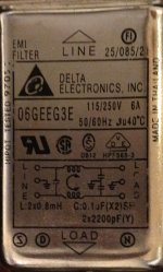
I'm looking at power entry line filters. Specifically, the Schurter KMF series. They come in a general purpose kind (with both X and 2Y capacitors) and a medical kind that doesn't have the 2Y capacitors (from line, neutral to ground on the "inside" of the filter).
In the medical field, the 2Y capacitors are omitted to eliminate ground current (I believe, correct me if I'm wrong). In audio, one could argue that having the 2Y capacitors would allow the HF line noise would get injected into the system ground, which may be undesirable. But I'm not sure how much this matters - if it's real at all.
Neither type offers that much attenuation at audio frequencies. Some of the best ones have, maybe, 20~25 dB attenuation at 10 kHz. The medical types are generally more expensive but offer worse attenuation above 1 MHz.
So my question is basically, which filter should I choose and why?
~Tom
Get the medical version. You get enough of the ones tied to ground and you'll get all sorts of junk you don't want. In a Hollywood dun house we had that problem and solved it by running the 120 VAC as balanced line 60-60 Volts because we had hundreds of machines with those unwanted caps and it was easier to balance the AC than to open all those units and change the filters.
G²
Folks,
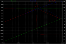
There seems to be a couple of different filter topologies out there. There's the "general purpose" vs "medical" (i.e. with/without Y caps) as well as a version with two common-mode chokes. The latter seems to do a good job of filtering out "garbage" trying to escape the equipment via the power line.
In my sim sheet, the three circuits represent (top to bottom): Line filter without Y caps (I use 1 pF Y caps to include some stray capacitance); line filter with Y caps; line filter with two common-mode inductors.
It's pretty clear from the results that the medical filter offers the best performance for keeping the noise out of the ground loop. This is hardly a surprise. The filter with two CM inductors offers good performance as well. In a real filter, I would imagine that the resonances are better controlled than what I show in my sim, hence, the attenuation is better than shown in my sim. Also, as expected, the "general purpose" filter offers the worst performance for noise currents in the ground path.
~Tom
Attachments

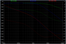
Now, for rejection of common-mode signals coming from the power line into the equipment, the general purpose filter offers better filtering than the filter without the Y caps. No surprise here either.
The filter with two CM inductors offers far superior performance. I think this filter type may be the best compromise between input filtering and ground loop noise suppression.
~Tom
The filter with two CM inductors offers far superior performance. I think this filter type may be the best compromise between input filtering and ground loop noise suppression.
~Tom
Attachments

A snubber on the amplifier should dampen the spikes coming down the line.
Just so we're on the same page: Snubber = resistor in series with capacitor. The snubber would connect from line to neutral across the power inlet connector. Am I understanding you correctly?
Which values of R, C would you recommend as a starting point?
It'll be far less expensive to just buy a filter. You're likely to get better performance from an off-the-shelf filter as well. Just sayin'...
~Tom
Very good solution, I applaud you G²!Get the medical version. You get enough of the ones tied to ground and you'll get all sorts of junk you don't want. In a Hollywood dun house we had that problem and solved it by running the 120 VAC as balanced line 60-60 Volts because we had hundreds of machines with those unwanted caps and it was easier to balance the AC than to open all those units and change the filters.
Some of Jim Brown's many papers are on line filters.
Audio Systems Group, Inc. Publications
http://www.audiosystemsgroup.com/PowerFilters.pdf
Audio Systems Group, Inc. Publications
http://www.audiosystemsgroup.com/PowerFilters.pdf
Just so we're on the same page: Snubber = resistor in series with capacitor. The snubber would connect from line to neutral across the power inlet connector. Am I understanding you correctly?
Which values of R, C would you recommend as a starting point?
~Tom
You are correct about the concept. There is probably some kind of calculation but a good starting point is 0.1uF in series with 100 ohms. Mouser sells snubber modules with the resistor and capacitor together.http://www.mouser.com/catalog/catalogusd/645/1029.pdf
I have noise being generated by my HPNA network. I am in the process of building solid state preamp with a toroidal transformer and regulators.
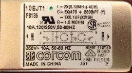
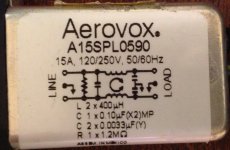
Which one of these will perform better?
Which one of these will perform better?
Attachments
Dude. All the component values are listed on those filters. Just set up a simulation... Or look up the attenuation graphs in the data sheet.
Which one wins all depends on which frequency range you're interested in suppressing. But if you want a shot-in-the-dark guess, I'd go with the one with two inductors. So the one on the left in the post above.
~Tom
Which one wins all depends on which frequency range you're interested in suppressing. But if you want a shot-in-the-dark guess, I'd go with the one with two inductors. So the one on the left in the post above.
~Tom
Last edited:
You are correct about the concept. There is probably some kind of calculation but a good starting point is 0.1uF in series with 100 ohms. Mouser sells snubber modules with the resistor and capacitor together.http://www.mouser.com/catalog/catalogusd/645/1029.pdf
Whacky. I had no idea those even existed. Nice find. Thanks for the link.
~Tom
- Status
- Not open for further replies.
- Home
- Amplifiers
- Tubes / Valves
- Line filters