Yes Dadod. To incorporate a regulation directly in a amp board (Like a SSA), the power regulator transistor in each amp rail next to the power devices, with no or very little cap, and incorporate this detection idea. But it is an other project, (i hope we can do that with L.C.), as this one is a stand alone protection.What do you think about this PS regulator integrated with the speaker protection and short circuit protection. http://www.diyaudio.com/forums/powe...iplier-electronic-protection.html#post2901733
I use it with my TT amp and it works quite good, ones prototected my speaker after an error in the amp.
HELLO
We need Alex here soon...
Hi Alexmm
greetings your the MAESTRO when it comes to pcb designing please something for us all really a nice project to make
warm regards
andrew lebon
We need Alex here soon...
Hi Alexmm
greetings your the MAESTRO when it comes to pcb designing please something for us all really a nice project to make
warm regards
andrew lebon
Suggested parts as requested.
Input solid state static relay:
G3VM PCB Omron. ( MOS FET Relays G3VM-351B/E | MOS FET Relays | Signal Relays | Relay | Products | OMRON Electronic Components Web)
Power static relay:
Sharp 8A Solid State Relay like S202S02 series ( http://www.sharpsme.com/download/s202s02-epdf )
Power Mosfets
IRF3710 (http://www.irf.com/product-info/datasheets/data/irf3710.pdf ]
optoisolators:
Panasonic APV1121S ( http://www3.panasonic.biz/ac/e_download/control/relay/photomos/catalog/semi_eng_apv.pdf )
Any better suggestion welcomed.
Last edited:
There is a little delay. This delay is constituted by the internal impedance of the output of U3 and the 0.22µf . Short !My question was about clipping. When an amp clips, the divided-down output falls short of the input and that should trigger the protection. If it doesn't, the protection doesn't do its job.
So you probably would want a delay to make sure that short-time clipping (and EVERY amp clips short-time during music play) doesn't lead to what John calls nuisance tripping.
Are you sure there's no delay of some sort in your protection?
But there is an offset you can tune. You can allow, for example, 5V rms ( = 7V peak) of error in your amp output with no risk to your tweeters (3Watts). or even more, because it will not stay more than some milliseconds.
But, if you are really aware of the clipping problem, the solution is very simple. You can add a peak limitation before the input of the amp witch will clip the input signal a little under the amp maximum excursion. So it will be no difference at all between input and output whatever max signal, and protection will never fire for clipping reasons. So easy.
We can add that if you need-it for a low quality PA systems, by example.
But, in fact, i was never in need of that, until now. Even with a big offset the protection has always fired instant in case of short circuit. and i would never allow my system to run in protection, while i'm listening music. ;-)
I tried to find the thread of a similar system that was introduced about 2 years ago and I implemented something similar also about two years back designing a ZUS amplifier protection system. It actually works very well and I used comparators as opposed to op amps. The inputs can be slowed down by RC networks because any difference will make the op amps in OGL mode respond. I just found that for commercial purposes the setting is too unforgiving, it would detect very small variations in differential signal and has to be desensitized to work adequately. It should be given hysteresis as well as delay, in other words the error must occur for at least x-time before the relay cuts in.But yes it is probably the ultimate way to protect an output from amplifier misbehaving as well as a user connecting funny loads at the end of it such as too low speaker impedance or short circuit.
Last edited:
1- I'll sue you for copy 🙂1- I tried to find the thread of a similar system that was introduced about 2 years ago and I implemented something similar also about two years back designing a ZUS amplifier protection system.
2- It actually works very well and I used comparators as opposed to op amps.
3- The inputs can be slowed down by RC networks because any difference will make the op amps in OGL mode respond. I just found that for commercial purposes the setting is too unforgiving, it would detect very small variations in differential signal and has to be desensitized to work adequately. It should be given hysteresis as well as delay, in other words the error must occur for at least x-time before the relay cuts in.
4- But yes it is probably the ultimate way to protect an output from amplifier misbehaving as well as a user connecting funny loads at the end of it such as too low speaker impedance or short circuit.
2- I prefered Op amps, because i wanted tu use the same can amplify and compare. (TL074). But, for sure, comparators are better to... compare.
3- In fact, you play music with your charge at highest level you can use: the protection fire. Then you tune the gain pot of the protection until it does not fire any more: done.
If it happens some time later because you're dead drunk with friends that it fires again, reduce a little more after your next morning's aspirin and forget.
4- It is. It alert-you you too if for some reasons (charge, RF, cap's age) your amp start to oscillate, even at pretty low level.
Christophe,
I don't mean to discourage you please carry on, I just tried to highlight small issues I had. The only resistance that you may find from audio fanatics are that you are tapping into the small signal audio path. If the impedance is sufficiently high it should not be of any concern.
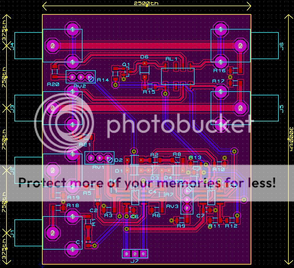
Please complete your protector as it is very worthwhile, develop a PCB and make it into a project - ever so often someone is looking for a protection circuit.
I am sure if it is offered as a stand alone PCB with relays etc, you may find quite a bit of interest here.
I don't mean to discourage you please carry on, I just tried to highlight small issues I had. The only resistance that you may find from audio fanatics are that you are tapping into the small signal audio path. If the impedance is sufficiently high it should not be of any concern.
Please complete your protector as it is very worthwhile, develop a PCB and make it into a project - ever so often someone is looking for a protection circuit.
I am sure if it is offered as a stand alone PCB with relays etc, you may find quite a bit of interest here.
I just use a simple PIC micro to monitor the output voltage.
If it goes above/below 20 volts for greater than 500ms it immediately shuts down the output relay.
Except output relays are not fast enough to protect the amp or most speakers. Only a crowbar is, but it will blow the amp before it blows the main fuse. Catch-22. You have to decide which costs more, the speaker or the outputs, and design for that. You won't get both. Maybe a massive class A amp could sustain full rail DC long enough to blow the power supply fuses and drain the main bank through a crowbar, matched to a massive woofer that can take all the amp has. Not a typical match. Protection seems to be one of those simple ideas that is darn hard to do.
Except output relays are not fast enough to protect the amp or most speakers. .
I cant agree. I design, build and sell amps and have used the PIC protection circuit on my test rig for a few years now. Despite having a few amps fail the speakers have never failed because the PIC was quick enough to turn off the output relay before the speakers fired. Speakers will take a while to heat up and fry and if your quick you will save them. I have 500ms timeout on the voltages staying out of spec and that works great.
I would certainly agree that you cant protect the amp in time as the amp going faulty usually causes the problem.
Don't worry, Nico, i was joking.I don't mean to discourage you please carry on, I just tried to highlight small issues I had.
And i''m ready to ignore the audiophile complaints against the sound degradation across the relay, or due to 10K+mosfet extra charge in the input ;-)
As the same causes produced the same effects, i was aware of the false positive due to thecounter-electromotive force of the speaker (is that a correct translation ?), and both hysteresis and (slight) delay is yet implemented.
For the moment, i'm asking myself if it can be useful to add two LM432 and two trimers, in order we can clip the input signal in our protection, before we apply-it to the amp, and near the max level the amp is able to deliver. In order that the amp can never saturate by itself, so never a clipping error, whatever the sensitivity. But it is > 2.5V. too high ?
Is this the basic idea?
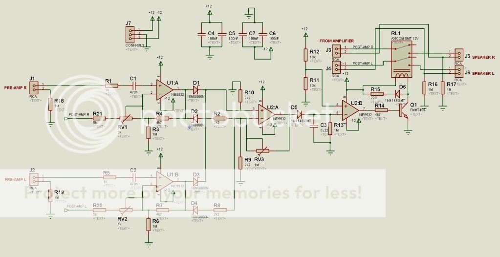
I think the elaborated circuit is a bit too elaborated, this is what I saw as the basic idea minus the optos and solid state relay crowbars and PSU details.
Could probably do with a relay with a bit more capacity than the one I've drawn in...
Forum has squashed these images, they're taller if you click on them.
There are some minor changes, some of which can be undone simply by using zero ohm links. Could be some errors in copying. What does anybody think?
View attachment protection_cct_2 - CADCAM.ZIP
I cant agree. I design, build and sell amps and have used the PIC protection circuit on my test rig for a few years now. Despite having a few amps fail the speakers have never failed because the PIC was quick enough to turn off the output relay before the speakers fired. Speakers will take a while to heat up and fry and if your quick you will save them. I have 500ms timeout on the voltages staying out of spec and that works great.
I would certainly agree that you cant protect the amp in time as the amp going faulty usually causes the problem.
That's my experience also. BTW There are a few threads here on bidirectional solid state relais that use MOSFETs and switch in a couple of uSeconds. Their Rdson is even lower than the resistance of a mechanical relay and also quite linear, so for sound quality there are quite good. Maybe that would be the ultimate solution?
jan
Its worth a try.
A speaker wont blow up immediately if you apply full B+ or B-.
It should take a low frequency OK.
Its a matter of catching it before it gets to the point where the DC is starting to fry the voice coil which is probably about a second.
A speaker wont blow up immediately if you apply full B+ or B-.
It should take a low frequency OK.
Its a matter of catching it before it gets to the point where the DC is starting to fry the voice coil which is probably about a second.
It look likes at first sight. Will comment after deeper examination.Is this the basic idea?
I recommend quad op amps because this is just an auxiliary board, the littlest the better. Better with surface components ?
The loudspeakers Mos relays are, as well as the mechanical relay, optional. You can chose to use one of them, or both together. i believe both are better.
For the mechanical relay, it is better to use the biggest you can find, low serial impedance, two contacts for each channel.
The input mosfet is requested for short circuit loudspeaker lines situations when mechanical relay is used.
that's what I thought, proposing to use them in // or not with mechanical relays, which can add a better linearity.There are a few threads here on bidirectional solid state relais that use MOSFETs and switch in a couple of uSeconds. Their Rdson is even lower than the resistance of a mechanical relay and also quite linear, so for sound quality there are quite good. Maybe that would be the ultimate solution?
To get rid of the clipping problem, i propose a solution. The problem i that, when the incoming amp level is too high, it can fire the protection, because the amp clips and, so there is a difference between the input and output signal in it. can be nice for home, bad for PA. The idea is to clip the signal just under this point, before it incomes in the amp.
Using this very simple circuit, see attached)
The upper LM431 is tuned by his R1 to limit the negative amplitude of the input signal. The bottom LM431 to limit the positive input signals. both will need to be tuned , according to your amp power capability, just before its maximal excursion.
One channel shown.
Attachments
+- full voltage (short circuit of a power transistor) can destroy instant your boomer's coil if the coil hit the back magnet plate. Too, fragile tweeters can be destroyed by this transient . They even can be destroyed by clippings.Its worth a try.
A speaker wont blow up immediately if you apply full B+ or B-.
It should take a low frequency OK.
Its a matter of catching it before it gets to the point where the DC is starting to fry the voice coil which is probably about a second.
This fast protection can be tuned according to your system roughness.
The idea is to provide a complete protection circuit, that you can populate or not according to your needs, to provide: Remote amp powering, Soft start, input limitation, DC input protection, use of MOSFET switch or/and mechanical relay, inside an amp, or outside in a separate box.
Last edited:
May-be this relay can be good (3 paralleled contacts):
Mini power relay-JQX-38F Power Relay supplies and manufacturer--China Naidian Group Co.,Ltd.
30ms operation, 30mΩ/3 = 10mΩ, 80A
Mini power relay-JQX-38F Power Relay supplies and manufacturer--China Naidian Group Co.,Ltd.
30ms operation, 30mΩ/3 = 10mΩ, 80A
A little bit off-topic, I have a question regarding use of output capacitor for protection. How good is that to protect the speaker? Is there any issue with putting this cap in push-pull amp output? What is the effect with stability?
There are SSA (BJT) versions that requires output caps (high offset). For me output caps are fine as I have many high quality caps. So permanent cap protection will be fine?
There are some SSA versions that is not so stable (in simulation), I'm afraid the cabling to the cap will increase instability.
I'm going to build a 75V SSA that in simulation will oscillate with 47n capacitance in parallel with output load. I need a temporary protector while working with the real circuit. Yes I can use cheap speakers so what I need is actually to protect the Hitachis. What is the best way to protect the transistors (e.g. temporarily)? What are the major causes of their possible destruction?
Why the protector in this thread is different from others for external wiring, in relation with stability?
Output caps suffer from several problems. By definition they do not allow very low frequencies , so they add a serial impedance to the amp, reducing damping, where you want-it. If you chose a too big value; the charge will suffer from the charging current in them.
They are not perfect: they add an inductance and a serial resistance. This can destroy the hf performance a bit.
They produce a little distortion.
They are expensive, reduce their value with time and use, and you have to change them after 10 years...
They will not have an impact on the stability of an amp, here, the added serial resistance and inductance will reduce the effects of the capacitive loads.
The difference between this protection and most of the other is:
It do not have to sens any internal part of the amp. (Power supply current etc...)
It is 100 time faster.
It protect against more possible issues (low DC offsets, HF oscillations, and even clipping if you want)
Also, they introduce phase shift at low frequencies....
All in one, the reasons why we all try to live without them...
All in one, the reasons why we all try to live without them...
- Home
- Amplifiers
- Solid State
- An ultimate amp protection circuit ?