Salas, what is the upper limit of voltage output for the REFLEKTOR. I have a Krell amp (KSA80B) that uses 75V in the input stage. Could something like the REFLEKTOR work there?
The added resistor that Roender is recommending goes before the first smoothing capacitor. (do you remember my rCRC recomendations?)
It can go between the rectifier and the smoothing cap or between the transformer secondary and the rectifier. Both of these locations are before the smoothing.
The PSU can be a simple C, or a CRC ,or a CLC, any of these work and all will work with the added R.
That added R is the reason I do not use big thick cables to connect the transformer to the PSU and through the PSU. I used to do that (40years ago) before I stated to think and simply copied what I saw others doing.
Just because you see something 100 times does not mean it is right. Sometimes what you see only once is better.
Last edited:
Salas, what is the upper limit of voltage output for the REFLEKTOR. I have a Krell amp (KSA80B) that uses 75V in the input stage. Could something like the REFLEKTOR work there?
If built with proper voltage & dissipation transistors it will.
What's differences between 1.2r and reflektor, sonically, of course? It's one better to supply digital or analog circuits?
1.2R is more ''forceful and round''. Reflektor has a nice balance of characteristics for something with less parts and easier to succeed. Rather ''open and clear'' its signature. Both are general purpose regs that I designed with analog in mind, though many people migrated them to digital. All types will need some care and checks that they are interfacing without reactions to the multitude of applications. They are not as held down as needed for something pass-partout without looking twice as a 3 legged chip reg. Although even an LM317 can be made much better interfaced to some load than just thrown there.
Hi Salas, is R7 (the 1k pot in the 5V Reflektor) the only adjustment one needs to make to obtain higher voltages (and Vin of course...)?
Its one transistor in the mirror that will particularly suffer also if going far beyond the voltages in the presentation examples. If within those margins then its just as simple as you say. Give me the details of voltage and peak current consumption of what you have in mind to do and I will let you know what to use.
1.2R is more ''forceful and round''. Reflektor has a nice balance of characteristics for something with less parts and easier to succeed. Rather ''open and clear'' its signature. Both are general purpose regs that I designed with analog in mind, though many people migrated them to digital. All types will need some care and checks that they are interfacing without reactions to the multitude of applications. They are not as held down as needed for something pass-partout without looking twice as a 3 legged chip reg. Although even an LM317 can be made much better interfaced to some load than just thrown there.
And how you will describe ver1.1 compared with the above versions?
250-300mA if you are sending up to 100-150mA to the load is good difference. With those parameters you are OK with the standard transistors. Use 5K trimmer with 1k2 series resistor in its tail and it should cover that range.
P.S. Hey where are some pics?
P.S. Hey where are some pics?
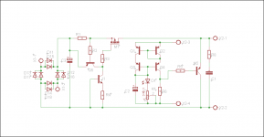
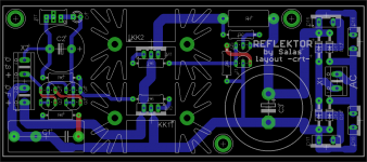
My initial refleKtor was a rough rats nest. I am designing a pcb in eagle and will post pics of board once populated. Do you have a ready pcb layout? I would iron it to pcb and etch.
I have got double layer with on board rectification and filtering. Maybe you can follow some ideas from it though. If you will have your raw DC part on a different board add a decoupling capacitor across the reg's board input.
Attachments
Thanks Salas, I tried last night and ended with a mess. Will use yours as a guide. How important is the heatsink on the M1. I understand the need for one on M2.
Very important. Remember you burn total CCS current times (Vin-Vout) on M1. You burn Vout times (totalCCScurrent-loadcurrent) on M2. Do the power calculations for any setting conditions in each app you got in mind and estimate thermals and sinks.
Hi AndrewThe added resistor that Roender is recommending goes before the first smoothing capacitor. (do you remember my rCRC recomendations?)
It can go between the rectifier and the smoothing cap or between the transformer secondary and the rectifier. Both of these locations are before the smoothing.
The PSU can be a simple C, or a CRC ,or a CLC, any of these work and all will work with the added R.
That added R is the reason I do not use big thick cables to connect the transformer to the PSU and through the PSU. I used to do that (40years ago) before I stated to think and simply copied what I saw others doing.
Just because you see something 100 times does not mean it is right. Sometimes what you see only once is better.
Would you care to elaborate on the Whys of using thin wire or using some resistance after the tx ?
- Status
- Not open for further replies.
- Home
- Amplifiers
- Power Supplies
- The simplistic Salas low voltage shunt regulator