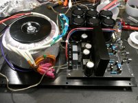
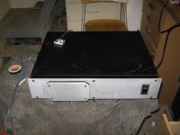
This is my first fore into building a Class D amp. I selected ready-made modules for the PSU and amp. I also selected this enclosure to house everything. It will be powered by a +-65VDC linear power supply. The enclosure is turning out to be a little snug, but using a linear PSU means a big fat torodial has to fit somewhere. 😛 I've powered it up and did not get any of the 'magic' smoke. I measured the DC-offset and got -.7mv on the left and -1.9mv on the right. Here are a few pictures of my progress.
Attachments
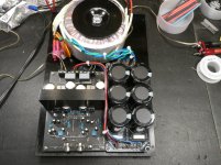

Neat work. I'm just finishing up my implementation of the same board, but I'm using four channels and two PSUs. One thing I did note is that the overtemp sensor isn't really connected to the heatsink, so I drilled a snug fitting hole further up the heatsink and extended it to fit. It does run slightly warmer than I was expecting, but I suspect that's down to the TIP31s.
edit: Here's a few pics;
edit: Here's a few pics;
Attachments

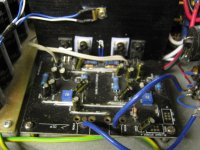
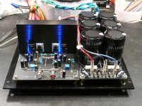
What's that sensor under the little brass bracket further up on the HS? Is that another one you moved? With 4-channels yours is a beast for sure. 😛
I was able to power it up last night with speakers connected. Sounds fine to me so far with non-critical listening and source. I did notice a very slight amount of inductance hum. Hopefully, once I put it all together, finish up the wiring with proper grounding it will 'go away'.
I was able to power it up last night with speakers connected. Sounds fine to me so far with non-critical listening and source. I did notice a very slight amount of inductance hum. Hopefully, once I put it all together, finish up the wiring with proper grounding it will 'go away'.
That's a sensor for the fan speed controller. This amp may occasionally get pushed, and the heatsink is no way big enough for that without help.
I've also added the missing bridging op-amp and bits, and cut some traces so one side is permanently inverting to avoid bus-pumping. I also cut holes for and mounted XLRs, but haven't fitted the balanced input circuits yet.
I've also added the missing bridging op-amp and bits, and cut some traces so one side is permanently inverting to avoid bus-pumping. I also cut holes for and mounted XLRs, but haven't fitted the balanced input circuits yet.
I see. That makes sense if you plan on pushing the amp a little harder. I'll be using my board pretty much stock. Sounds like you can customize a bit more than I'm comfortable with - but I'm learning. 😛
I had it playing a CD tonight on my bench and within about 30 minutes the HS was very hot to the touch. I was surprised since I was playing at a very low to medium volume level. 😕 Is it due to the fact that this HS is underrated for a typical operating environment? Odd. I know this is rated at 250wpc, so maybe I should be playing it louder! 😛
I had it playing a CD tonight on my bench and within about 30 minutes the HS was very hot to the touch. I was surprised since I was playing at a very low to medium volume level. 😕 Is it due to the fact that this HS is underrated for a typical operating environment? Odd. I know this is rated at 250wpc, so maybe I should be playing it louder! 😛
Here's my first guess:
Amp is rated for 8 ohms only. Were your speakers an 8 ohm nominal load?
Next culprit:
You might also want to measure the DC rails to see what you are actually pushing the amps with... the higher the rail voltage, the more dissipation might be taking place.
Finally:
You could have a high frequency (supersonic) oscillation causing the amps to heat up. You would need a scope to find that.
-Charlie
Last edited:
Mine is working hotter than expected as well, driving 8 ohm speakers at 64.3V. Won't get chance to put it on the scope 'till the weekend.
is it the output mosfet that's producing the heat or the regulator transistor?I had it playing a CD tonight on my bench and within about 30 minutes the HS was very hot to the touch. I was surprised since I was playing at a very low to medium volume level. 😕 Is it due to the fact that this HS is underrated for a typical operating environment? Odd. I know this is rated at 250wpc, so maybe I should be playing it louder! 😛
Yes, 8 ohm load and 64v rails. Don't have a suitable scope though. 🙁 I'm curious if this temp is standard operating spec. Mine will be in a vented enclosure, so maybe I have nothing to worry about, and then maybe something else is going on that needs attention.Here's my first guess:
Amp is rated for 8 ohms only. Were your speakers an 8 ohm nominal load?
Next culprit:
You might also want to measure the DC rails to see what you are actually pushing the amps with... the higher the rail voltage, the more dissipation might be taking place.
Finally:
You could have a high frequency (supersonic) oscillation causing the amps to heat up. You would need a scope to find that.
-Charlie
Last edited:
Everything is attached to the same HS, so not sure how I can detect what specific device is causing the heat.is it the output mosfet that's producing the heat or the regulator transistor?
Update.... I just got through doing the final wiring of my amp in the enclosure and it continues to blow a 3-amp fuse. It blows instantaneously. What is the typical in-rush of current for this board when first powered up? I've double checked my wiring and everything looks good. This was the first time using the IEC connector on the back with a 3-prong grounded plug. Is 3-amps to low? Should I be using at least a 5-amp, maybe even 10-amp fuse?
Edit: According to the Sure User's Guide that came with the amp, it looks like I need at least a 7.5amp fuse. If this is the standard operating current requirements, I'm thinking the start-up power may spike a little higher. Would that size of fuse be fair to use?
Edit: According to the Sure User's Guide that came with the amp, it looks like I need at least a 7.5amp fuse. If this is the standard operating current requirements, I'm thinking the start-up power may spike a little higher. Would that size of fuse be fair to use?
Last edited:
Mine powers up fine with an 8A breaker, but I did use a soft-start circuit, (top left, first pic) to reduce the initial surge from the twin traffos and capacitor banks.
I've got some 8 and 10amp fuses on order. No place locally to buy them cheap. 🙂 I have a couple of soft-start boards, but ran out of room inside my case. If the 8 or 10amp fuses don't work, I may have to implement the soft-start option. Hum... where will I put it.😛
I found a 6.3amp fuse at RatShack today. Popped it in and it survived the startup current and worked fine.
Based on FTC?... I don't understand.did you test this amp based on FTC? would be interested in the actual power capability...
Somehow I missed this thread until now.
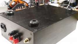
With the heat sink finning horizontal, natural convection is largely ineffective.
A small fan blowing along the fin direction would do the trick.
With the heat sink finning horizontal, natural convection is largely ineffective.
A small fan blowing along the fin direction would do the trick.
I had it playing a CD tonight on my bench and within about 30 minutes the HS was very hot to the touch. I was surprised since I was playing at a very low to medium volume level. 😕 Is it due to the fact that this HS is underrated for a typical operating environment? Odd. I know this is rated at 250wpc, so maybe I should be playing it louder! 😛
Mine is fan cooled, but even so for any heavy use at full power I'd want to seriously beef up the heatsink.
- Status
- Not open for further replies.
- Home
- Amplifiers
- Class D
- Sure Electronics IRS2092 250wpc Amp Build