Hi Kindhornman
While I did not use the customary words, my interest is entirely in how things work and so my explanation followed that line of thought, its operation acoustically, instead of tradition.
You are sort of right with your example, a coax driver where the hf unit “speaks” through the center of the cone can be considered a horn based on what it does BUT horn loading ceases (see the radiation resistance curve) when a radiator is larger than about 1/3 wavelength in diameter so the acoustic impedance transformation is over and done before the radiator is radiating a frequency where it is small compared to the wavelength.
Similarly, for a one inch compression driver, the impedance transformation up high is over and done well before the sound even reaches the exit as the wl at 20KHz is only about 5/8 inch.
Fwiw, the root of the Unity and Synergy horns came from a comment Don Davis made at a Synaudcon meeting in the early 90’s where he commented that the conical horns have the advantage of being near constant directivity BUT had the down side of poor LF loading.
Some 12 years later it dawned on me why that was (the rate of expansion governs how low in frequency the horn couples to the transformation) and that triggered placing the mid drivers on the horn where the expansion rate had slowed to more like a mid horn etc.
Best,
Tom Danley
but wouldnt this definition call the wall, or the corner a waveguide of you place the speakers close to it? I mean i've heard the term corner loading, but to stretch it to horn loading? it does seem rather tenuous, It meets the strict definition sure, but in the same way that white is a colour…
Isn't it the old ambiguity between "it looks like ..." and "it works like ..."? In this forum I would like to see things discussed by their working principles rather than their look alikes. 🙂 😉
Rudolf
Rudolf
Hi qusp
A boundary or set of boundaries like a wall / wall / floor junction can exhibit “horn loading” and confines the radiation angle to fractional space like a horn does. It can do this coherently when the source of sound is no farther from the boundary than about 1/6 Wavelength. The reason is the sound pressure spreads where ever the surrounding pressure gradient allows and does so at the speed of sound. When a boundary reaches ¼ wl from the source, the returning reflection is delayed ½ wl and so arrives out of phase and causes a cancellation notch there and every odd half wavelength for frequencies above that.
In the Synergy horns at work, this same cancellation notch determines the highest frequency the mid and woofers can operate to in the horn so their use is confined to the frequency ranges below that notch..
So far as the impedance transformation of a horn, that depends on the rate of expansion the pressure is confined to as it radiates from the source.
As I mentioned there is a “high pass” function to this which is tied to that rate of expansion so it depends on the geometry and how large the enclosure is etc.
White is all the colors!
Best,
Tom
DBMandrake,
Tom touched on and you are completely incorrect and that is why I brought up the cone driver as a horn. It is done by more than one company and Tannoy is famous for this, so you need to think before you make a statement like you did. A cone with a compression driver behind it is considered a waveguide and it works up to the diameter of the cone. What I am saying is if we want to get into semantics we can skew the traditional definition of many things and all we do is confuse others who aren't looking for a literal meaning of the term but how it is used in this industry as a useful term. Now I guess you could take it to the extreme here as Tom did, not really Tom but I guess DB Keeele who did that but it would not be a generally accepted use of the term. No different than the joke that Markus used to describe his cardboard baffle, technically correct but not what would be acceptable terminology in the industry or by the majority of people. I guess you should go back about a hundred years and read Websters definition of a horn loaded loudspeaker, that is what is generally acceptable terminology. Anyone who understands the working of the acoustical loading of a horn waveguide understands that the best acoustical loading is either an exponential or hyperbolic expansion rate. One of the poorest as far as transfer function is the conic section. Tom is using the conic section for directivity issues not for maximum power transfer function.
Tom touched on and you are completely incorrect and that is why I brought up the cone driver as a horn. It is done by more than one company and Tannoy is famous for this, so you need to think before you make a statement like you did. A cone with a compression driver behind it is considered a waveguide and it works up to the diameter of the cone. What I am saying is if we want to get into semantics we can skew the traditional definition of many things and all we do is confuse others who aren't looking for a literal meaning of the term but how it is used in this industry as a useful term. Now I guess you could take it to the extreme here as Tom did, not really Tom but I guess DB Keeele who did that but it would not be a generally accepted use of the term. No different than the joke that Markus used to describe his cardboard baffle, technically correct but not what would be acceptable terminology in the industry or by the majority of people. I guess you should go back about a hundred years and read Websters definition of a horn loaded loudspeaker, that is what is generally acceptable terminology. Anyone who understands the working of the acoustical loading of a horn waveguide understands that the best acoustical loading is either an exponential or hyperbolic expansion rate. One of the poorest as far as transfer function is the conic section. Tom is using the conic section for directivity issues not for maximum power transfer function.
If we're interested in how wave guides work, then Simon got it right, especially in the context of the thread's title. The idea a flat baffle is 180 degree waveguide is not novel and has been discussed at DIYaudio before.
These days, given the cheapness of amplification, who cares about horn loading for domestic use? What I want, (since I have a normal living room), is controlled directivity and no nasty surprises in the off axis FR.
Danley's horns may be even better from this point of view (small room) because the multi driver lobing problem is diminished to vanishing point and a DIYer can deal with the HOMs using Geddes's foam filter.
DBMandrake,
Tom touched on and you are completely incorrect and that is why I brought up the cone driver as a horn. It is done by more than one company and Tannoy is famous for this, so you need to think before you make a statement like you did. A cone with a compression driver behind it is considered a waveguide and it works up to the diameter of the cone. What I am saying is if we want to get into semantics we can skew the traditional definition of many things and all we do is confuse others who aren't looking for a literal meaning of the term but how it is used in this industry as a useful term. Now I guess you could take it to the extreme here as Tom did, not really Tom but I guess DB Keeele who did that but it would not be a generally accepted use of the term. No different than the joke that Markus used to describe his cardboard baffle, technically correct but not what would be acceptable terminology in the industry or by the majority of people. I guess you should go back about a hundred years and read Websters definition of a horn loaded loudspeaker, that is what is generally acceptable terminology. Anyone who understands the working of the acoustical loading of a horn waveguide understands that the best acoustical loading is either an exponential or hyperbolic expansion rate. One of the poorest as far as transfer function is the conic section. Tom is using the conic section for directivity issues not for maximum power transfer function.
of course its been mentioned here before, gratuitous intellectualization (apparently not a word) is rampant on these forums. it DOES meet such a wide definition, but I really think its taking it too far and makes the term meaningless, stick a little tweeter in my belly button and you can call ME a waveguide.
Why have the term at all when all baffles, woofer surrounds, tweeter faceplates, a naked driver facing vertically on the floor and many rooms can be called a waveguide? how about an empty room with a large naked dipole sub that happens to have a pole supporting the ceiling, placed behind but in a position that it shapes some of the very long wavelengths and results in a smaller aperture than if it wasnt there? where do you draw the line?
i'm about as far from an expert in this area as its possible to get and i'm here to learn; its my sense of reason thats gotten me this far without any training. I understand the concept, but such a 'definition' fails to usefully define. Someone just grappling with the concept of horns and WG's could quite easily come away more confused than going in.
Last edited:
Don't know why the usefulness is questioned. What we perceive is the room/speaker system. It can't be separated. So what's wrong about an approach that includes more than just a loudspeaker with some stuff attached to it under free field conditions?
Last edited:
Along the lines of boundary loading, I'd like to float a question/idea from the 'Suitable midrange cone for bandpass Unity horn' thread. Using vertical/horizontal symmetry, you should be able to use infinite boundaries to cut the Synergy horn into several pieces. An infinite boundary on axis transforms real sources into mirror sources. With perfect symmetry the physics should be unchanged.
Exploiting this, I expect that I should be able to experiment with mids/slot sizes etc by using only part of a unity horn and closing it using boundaries (the floor, wall). To an extreme, one wedge closed against an L-shaped boundary would work.
At this point it may only be a curiosity. But if, like me, you listen from close to the floor, it makes sense to use this boundary to close the horn. This should have the same effect as listening at the midpoint of a room that is twice as high. It's an idea that I'd like to pursue.
An externally hosted image should be here but it was not working when we last tested it.
Exploiting this, I expect that I should be able to experiment with mids/slot sizes etc by using only part of a unity horn and closing it using boundaries (the floor, wall). To an extreme, one wedge closed against an L-shaped boundary would work.
At this point it may only be a curiosity. But if, like me, you listen from close to the floor, it makes sense to use this boundary to close the horn. This should have the same effect as listening at the midpoint of a room that is twice as high. It's an idea that I'd like to pursue.
Don't know why the usefulness is questioned. What we perceive is the room/speaker system. It can't be separated. So what's wrong about an approach that includes more than just a loudspeaker with some stuff attached to it under free field conditions?
I completely agree that the room and speaker interface cannot be separated, but the term waveguide should and has always been used to define a specific object, not an environmental effect. how is a name for an object useful if it can be used to describe just about anything in the speakers immediate environment? how do you then point to the waveguide?
Last edited:
Along the lines of boundary loading, I'd like to float a question/idea from the 'Suitable midrange cone for bandpass Unity horn' thread. Using vertical/horizontal symmetry, you should be able to use infinite boundaries to cut the Synergy horn into several pieces. An infinite boundary on axis transforms real sources into mirror sources. With perfect symmetry the physics should be unchanged.
Exploiting this, I expect that I should be able to experiment with mids/slot sizes etc by using only part of a unity horn and closing it using boundaries (the floor, wall). To an extreme, one wedge closed against an L-shaped boundary would work.
At this point it may only be a curiosity. But if, like me, you listen from close to the floor, it makes sense to use this boundary to close the horn. This should have the same effect as listening at the midpoint of a room that is twice as high. It's an idea that I'd like to pursue.
yeah I have been thinking about this too, as a way to utilize the most space in small rooms, if you owned the house, you could actually use the floor->wall and corners to create soffit-mounted unity type horns
I completely agree that the room and speaker interface cannot be separated, but the term waveguide should and has always been used to define a specific object, not an environmental effect.
If you want to talk about a horn attached to a compression driver then nothing that has been said keeps you from doing so. This doesn't change the fact that the "horn model" is obviously applicable in a broader sense. As with all models, the question is its validity.
yeah I have been thinking about this too, as a way to utilize the most space in small rooms, if you owned the house, you could actually use the floor->wall and corners to create soffit-mounted unity type horns
Living inside a horn? Sounds interesting 🙂
Is the approach practical? A horn with a closed mouth?
Which is completely irrelevant to what I was saying. Yes a concentric driver like a tannoy uses the cone of the driver to act as a waveguide for the tweeter in the middle, so what ? It doesn't change the fact that a large baffle which the driver is mounted on can also be a waveguide at the same time, you can have waveguides within waveguides...Tom touched on and you are completely incorrect and that is why I brought up the cone driver as a horn. It is done by more than one company and Tannoy is famous for this, so you need to think before you make a statement like you did. A cone with a compression driver behind it is considered a waveguide and it works up to the diameter of the cone.
Imagine an extreme example - a whizzer cone full range driver mounted on a large flat baffle.
The large baffle is acting as a 180 degree waveguide down to some lower midrange frequency set by the baffle size. Within the driver itself the main cone of the speaker is acting as a conical waveguide for the whizzer cone radiation, down to some frequency set by the size of the cone (just like the tannoy) and if it has a radiating dust cap the whizzer cone is acting as a waveguide/horn for the radiation from the dust cap as well, down to a frequency set by the size of the whizzer cone. (Except whizzer cones are often near exponential in shape rather than conical, at least in good full range drivers)
A lot can be happening at once. Just because the cone itself might be working as a waveguide doesn't mean there can't be a bigger one around it operating to lower frequencies. (The baffle)
Don Keele wrote the seminal papers on non-exponential horn profiles, if its good enough for him (and Tom Danley) its good enough for me! Sorry. 😉What I am saying is if we want to get into semantics we can skew the traditional definition of many things and all we do is confuse others who aren't looking for a literal meaning of the term but how it is used in this industry as a useful term. Now I guess you could take it to the extreme here as Tom did, not really Tom but I guess DB Keeele who did that but it would not be a generally accepted use of the term.
Understanding of horn loading and waveguide design has come forward in huge leaps and bounds in the last 100 years. I don't take much stock in a definition that was written before the operating principles of the device were properly understood. More in depth understanding of waveguide design has only been around for just over 30 years or so, largely thanks to Don Keele.No different than the joke that Markus used to describe his cardboard baffle, technically correct but not what would be acceptable terminology in the industry or by the majority of people. I guess you should go back about a hundred years and read Websters definition of a horn loaded loudspeaker, that is what is generally acceptable terminology.
I fail to see how this alters the discussion of whether a flat baffle is a waveguide ?Anyone who understands the working of the acoustical loading of a horn waveguide understands that the best acoustical loading is either an exponential or hyperbolic expansion rate. One of the poorest as far as transfer function is the conic section. Tom is using the conic section for directivity issues not for maximum power transfer function.
Nobody has said that we are trying to achieve optimal acoustic loading ? Yes of course Tom is using a conical section for directivity not loading, all constant directivity waveguides are conical over most of their length. So what ?
Horns and waveguides are the same thing, just with different parameters optimised. A "horn" optimises acoustic impedance transformation, a "waveguide" optimises pattern control, however you will always have at least some of both happening in any given device, eg even a constant directivity waveguide still provides some loading / impedance transformation, although much less than exponential.
Nowadays emphasis is on pattern control rather than maximising acoustic impedance transformation, so the term waveguide is usually more appropriate, and I use it here for a flat baffle as well as the main effect is pattern control (to 180 degrees) and the amount of acoustic transformation / loading is quite small. (equal to 3dB)
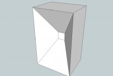
Let me show you a few pictures quickly mocked up in sketchup. The first is a baffle with a taper towards the centre - excuse the square driver instead of round, it should still give the idea.
Would you agree this first image is a waveguide ? Of course it must be. It has a throat, a mouth and an exit angle of less than 90 degrees. The driver sees a constrained section of solid space - less than 180 degrees. DI will be greater than 3dB. Directivity will be narrower than 180 degrees.
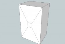
Image two is the flat baffle. Is this a waveguide ? Solid space is still constrained to 180 degrees, DI is 3dB, exit angle is 90 degrees.
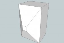
Now look at image three, what is this ? Exit angle is greater than 90 degrees, solid space seen by the driver is more than 180 degrees but less than 360 degrees. DI will be less than 3dB but greater than 0dB. Directivity will be greater than 180 degrees but less than the 360 degrees of an infinitely long tube.
They're all just variations on the same thing. All can be modelled in hornresp because they all follow the same fundamental operating principles. Of course image 3 is not something that you would actually build because its a worse waveguide than even a flat baffle. 😉
If it offends your horn sensibilities that a flat baffle is actually a horn/waveguide (albeit a fairly poor one) then I'm sorry but that can't be helped.
Attachments
Last edited:
I remember that, yes. Yet, the level of first order reflections is very well perceivable as stonger or less ASW or spaciousness. I am just experiencing that live with the two versions of my omni. So that point is subject to preference.
stonger ASW/spaciousness etc. is nothing bad, in particular it is nothing inaccurate or un-HiFi
but yes it is a matter of personal preference eventually
I should have said increased ratio of direct/reflected sound. That does exist.
yes I don't question the fact that such deteroriation of the quality of reproduced sound may occur but still we don't know why this increased ratio causes all those audible problems
after all the first wavefront remains the first wavefront
exactly why I have a problem, with this 'definition' (we are now stretching the term definition) you can call 3 and other situations, shapes like it, a horn and thats patently ridiculous. you could mount a driver on the small end of a pole and call the pole a horn
Last edited:
Indeed, although the speakers in his simulated room were pretty far from the "walls". One has to be careful to generalize his conclusions to all small rooms.
If a speaker is placed closer to the walls, the rear wall may introduce audible colouration (just like the floor reflection in some cases). Side wall reflections may introduce image shift/blurring or perhaps colouration (very early reflections).
floor reflection is always a problem for conventional forward radiating speakers
The side wall reflection is something that may depend on personal taste. Image shift/blurring is a negative aspect for some, while others may find the effect to be pleasantly spacious. The majority seems to like it.
exactly, the "image shift/blurring" that side-wall reflection produces can be described in more neutral terms as increased ASW and spaciosuness (lowered IACC) which many (if not most, as studies by Toole and by Bech as well seem to suggest) listeners prefer
anyway, when Bech designed Beolab line of speakers he licensed an acoustic lense from Sausalito - which in case of Beolab 5 projects the sound into front 180 degrees horizontally and 30 degrees vertically so that the front wall reflection (from behind the speakers) and also floor and ceiling reflection are effectively taken out of the picture
Minimizing possibly harmful reflections (i.e. floor) while preserving other reflections might be the best approach.
this is exactly the flooder approach discussed here: http://www.diyaudio.com/forums/multi-way/121385-loudspeakers-room-system.html
I once heard a Beolab 5 and it was one of the worst listening experiences I've ever had. They were placed close to the front wall but far away from all other walls (>5-10ms).
Markus, what was the main problem for you, colouration or lousy imaging?
All of that. I couldn't even say what exactly was wrong because everything was wrong. And it didn't even sound spacious.
unfortunately B&O dealers are instructed by the marketing department to set bass EQ controls of Beolab 5 for any demontration to "max" position regardless of room, positioning, anything
and an overblown bass can spoil everything
I'm sure everyone was expecting something little bit more than FRS8 in a cardboard dipole
from that particular user? really? 😉
Actually a driver mounted on the end of an infinitely long cylinder (only just big enough in diameter to house the driver) is considered to be free space loading, not horn loaded.exactly why I have a problem, with this 'definition' (we are now stretching the term definition) you can call 3 and other situations, shapes like it, a horn and thats patently ridiculous. you could mount a driver on the small end of a pole and call the pole a horn
Don't get too hung up in terminology about what a "horn" is, it doesn't have to look like a trumpet to be a horn! As markus says, the horn model applies to more than things that just look obviously like a horn.
At the end of the day, does mounting a driver on a large baffle constrain the directivity ? Yes it does, to 180 degrees, above a frequency dictated by the size of the baffle.
Does it reduce the angle of solid space seen by the driver thus increase the radiation resistance and increase the efficiency ? Yes it does, by 3dB. (It divides free space into half above the cutoff frequency dictated by its size)
If it walks like a waveguide, quacks like a waveguide and smells like a waveguide, it is a waveguide. 😛
The problem with most narrow directive speakers is a collapsing polar response in the highs. I don't believe that's ideal and is practically an EQ. But for rooms where sidewall treatment isn't an option, it might be the best compromise. For those who can treat early sidewall reflections, I believe a more uniform polar response (not omni though) gives a better result.
Spaciousness can come from lateral diffusion in the back of the room. The combination of sharp and accurate stereo image with low levels of early reflections (RFZ) and diffusion in the rear gives IMO the best of two worlds. I don't think Toole every tried that in his experiments. That's LEDE in a nutshell by the way.
Spaciousness can come from lateral diffusion in the back of the room. The combination of sharp and accurate stereo image with low levels of early reflections (RFZ) and diffusion in the rear gives IMO the best of two worlds. I don't think Toole every tried that in his experiments. That's LEDE in a nutshell by the way.
- Status
- Not open for further replies.
- Home
- General Interest
- Room Acoustics & Mods
- Controlled vs wide dispersion in a normal living room environment..