Over on the latest Paraline discussion (http://www.diyaudio.com/forums/multi-way/217298-square-pegs.html), a member of the forum had requested an illustration of how the device works.
In order to understand the Paraline, you need to understand phase plugs.
So, I thought I'd post some illustrations of how phase plugs work, or at least how I personally understand them.
Some of this will be open to debate, so if you don't agree with my hypothesis, please post your arguments! I'm still learning this stuff.
The first thing we have to keep in mind, is basic quarter wave theory:
#1 - If we have two sources which are in phase, they will sum constructively as long as they're within about 1/4 wavelength
#2 - If we have two sources which are in phase, they will sum destructively (null each other out) when they're seperated by 180 degrees, or one-half wavelength
#1 - If we have two sources which are in phase, they will sum constructively as long as they're within about 1/4 wavelength
#2 - If we have two sources which are in phase, they will sum destructively (null each other out) when they're seperated by 180 degrees, or one-half wavelength

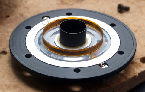
Here is a picture of a Dayton RS52 with the grill removed.

Here's an illustration that I made of the wavefront that's coming off of a Dayton RS52. The hemispherical shape at the bottom of the illustration is the RS52's dome. The arrows indicate the pathlength of sound radiating from the center and the edge of the dome. The funky yellow and purple checkerboard is there to make it easier for you to visualize the pathlength difference. Each square in the checkerboard is 0.5cm square.
From my last post, you'll recall that the sound of two radiators will null each other out when they're out of phase by one-half wavelength. I've coined a term for our phase plugs that I'll call our "margin of error." The margin of error is the distance at which the two radiators null each other out perfectly.
In the pic above, we see that the top of the Dayton RS52 is about 1cm higher than the edge. This means that the sound from the top of the dome will reach your ears sooner than the sound from the edge.
We can calculate when the null will happen. Here's the formula:
speed of sound / distance / 2 =
34000cm per second / 1cm / 2
= 17000hz
So the pathlength difference between the tip of the dome and the edge of the dome should cause a null at approximately 17000hz.

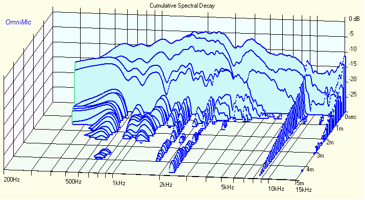
Here's a measurement of the RS52. (I stole the measurements and the pics from Dave Ralph at Speakerdesign.net)
In the graph, we see a deep, deep null about 18000hz. So this is consistent with what we would expect due to the phase difference.
Let me know if you have any questions about the null, why it happens, the geometry, etc.
One question you may have is why there's a big peak that precedes it. I believe that big peak is due to the 'ringing' of the aluminum dome.
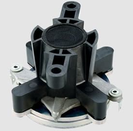
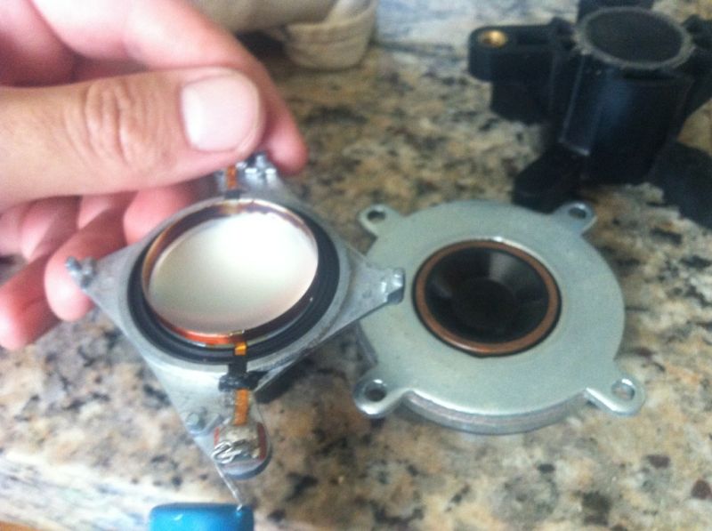
Here is a picture of a Celestion CDX1-1425 with and without the phase plug removed. You can see that without the phase plug it is little different than the Dayton RS52, albeit with a smaller lighter dome, and a much much much smaller back chamber. (The smaller back chamber raises the power handling, and ramps up the efficiency to a humongous degree at the resonance.)
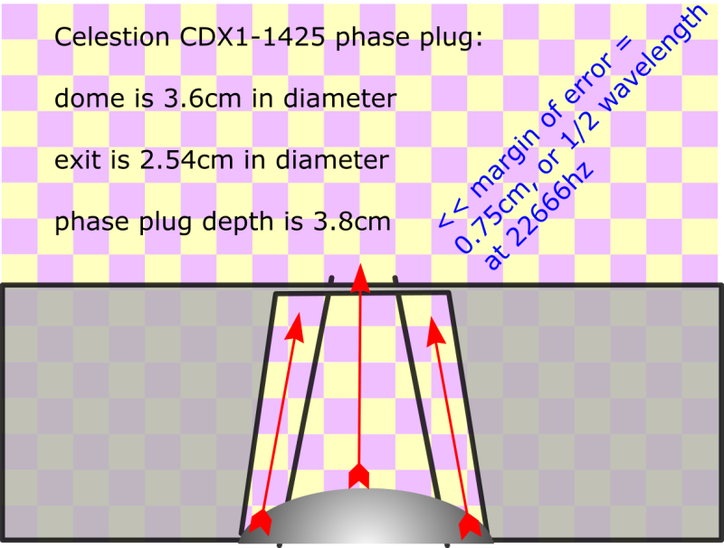
Here's an illustration that I made of the wavefront that's coming off of a CDX1-1425. The hemispherical shape at the bottom of the illustration is the compression driver's dome. The arrows indicate the pathlength of sound radiating from the center and the edge of the dome. The funky yellow and purple checkerboard is there to make it easier for you to visualize the pathlength difference. Each square in the checkerboard is 0.5cm square.
From my second post, you'll recall that the sound of two radiators will null each other out when they're out of phase by one-half wavelength. I've coined a term for our phase plugs that I'll call our "margin of error." The margin of error is the distance at which the two radiators null each other out perfectly.
In the pic above, we see that the top of the Celestion's dome is about 0.75cm higher than the edge. This means that the sound from the top of the dome will reach your ears sooner than the sound from the edge. The phase plug on the Celestion is a simple frustum (http://en.wikipedia.org/wiki/Frustum). The frustum simply takes the energy radiated off of the diaphragm and focuses it into an area that's 2.54cm in diameter. Very simple. When looking at the frustum-shaped phase plug, it might occur to you that the exit doesn't have to be that size, and this is true. If one used a frustum with a smaller diameter it might work fine. The trick is to keep the pathlengths equal. IE, if you used an exit which was 2" in diameter, it would not work as well, because the energy radiated by the dome would lead the edges by even more than it does now, and the null would move lower in frequency due to the pathlength difference.
We can calculate when the null will happen. Here's the formula:
speed of sound / distance / 2 =
34000cm per second / 0.75cm / 2
= 22666hz
So the pathlength difference between the tip of the dome and the edge of the dome should cause a null at approximately 22666hz.

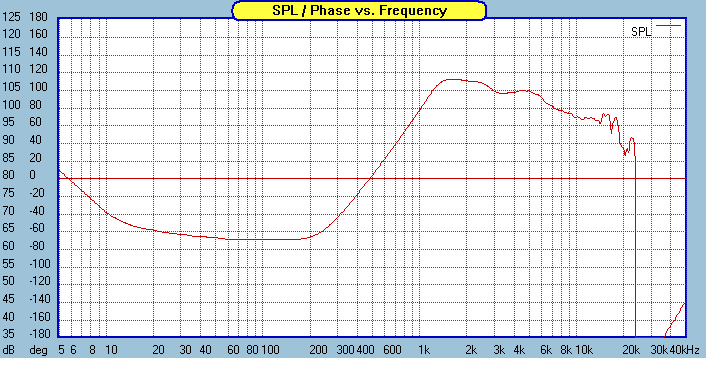
Here's a measurement of the CDX1-1425 on a horn. (I stole the measurements and the pics from Augerpro and Paul Spencer's blogs)
In the graph, we see a deep, deep null about 23000hz. So this is consistent with what we would expect due to the phase difference.
Let me know if you have any questions about the null, why it happens, the geometry, etc.
One question you may have is why there's a big peak that precedes it. I believe that big peak is due to the 'ringing' of the aluminum dome. This 'ringing' is especially noticeable in the CSD plot.
I personally prefer small compression drivers like the CDX1-1425 over large compression drivers like the Selenium D220ti. The reason that I prefer small compression drivers is that I find this 'ringing' audible. A horn filters out the high frequency output of a radiator, so the 'ringing' of an aluminum dome, when combined with a horn, often creates a response that's relatively flat. (In other words, if it wasn't for the horn, the 'ringing' of the dome would result in a giant peak like we see in the Dayton RS52 from my last post. The horn's rolloff, when added to the peaky response of a metal dome, yields something that's fairly flat.)
But it's easy to see the ringing in a CSD plot. For instance, here's the CSD from three drivers. Two use metal domes; one uses a plastic ring. You can see that the metal domes ring, and the ringing gets lower in frequency as the diaphragm gets larger.

BMS 4550 - plastic 4.4cm ring radiator

Celestion CDX1-1425 - aluminum 3.6cm dome

Selenium D220ti - Titanium 4.3cm dome
Basically, if you look at the CSD of these three drivers, the BMS has the best combination of size and CSD. The Celestion has arguably the best CSD of the three, though it comes at the cost of a smaller diaphragm, which raises the xover point and reduces maximum output.
Last edited:
Patrick, how does the frustrum even out the path lengths? It looks like me like the path from the outside of the dome has to go farther than without the frustrum.
Patrick, how does the frustrum even out the path lengths? It looks like me like the path from the outside of the dome has to go farther than without the frustrum.
The shortest distance between two points is a straight line. Therefore, the shortest distance in the CDX1-1425 would be a line that pointed straight UP. But then you've created a new problem - which is that the center of the horn entrance is out of phase with the edge of the horn entrance.
The ideal source is arguably a flat disc located right at the entrance to the horn. (IE, no compression driver at all, simply a flat disc at the throat.)
If you look at my illustration above, you'll notice that you can improve the pathlengths by narrowing the diameter of the dome, and by flattening it out. If you look at some JBL models you'll notice that their horn-loaded domes use a dome which is nearly flat, and I think this is the reason they do that.
To be honest, Patrick, since your drawings all show straight arrows, I don't see how the phase relation of the "center" and the "outside" of the wave becomes aligned. It looks as through the improvement is due the the simple fact that the Celestion has less curve to the dome.
Admittedly, this is something I know nothing about, but I thought phase plugs made the center of the wave travel farther than the outside (or rather, the same distance). I vaguely remember drawings of the tangerine when it was introduced.
Admittedly, this is something I know nothing about, but I thought phase plugs made the center of the wave travel farther than the outside (or rather, the same distance). I vaguely remember drawings of the tangerine when it was introduced.
Patrick, in this pic, wouldn't the path lengths of the blue and green match better than the red and green? It looks like the narrowing would make it worse, not better?

I thought I understood phase plugs (but maybe not?)
In general, I'm having a lot of difficulty getting the whole thing about the paraline-like structures being discussed. I can see the line source generation, but can it only produce lines sources?
I thought I understood phase plugs (but maybe not?)
In general, I'm having a lot of difficulty getting the whole thing about the paraline-like structures being discussed. I can see the line source generation, but can it only produce lines sources?
Last edited:
Patrick, in this pic, wouldn't the path lengths of the blue and green match better than the red and green? It looks like the narrowing would make it worse, not better?
I thought I understood phase plugs (but maybe not?)
In general, I'm having a lot of difficulty getting the whole thing about the paraline-like structures being discussed. I can see the line source generation, but can it only produce lines sources?
I'd argue to simply measure it. Literally make a pic of it in Xara (it's free) and measure the pathlength.
This is the Celestion CDX1-1425. If the diaphragm was flat the pathlengths would be better. If the dome was inverted, that would be the best of all. (The pathlength from the edge will *always* be long because it's not straight. So inverting the dome is an easy way to equalize the pathlength between the center and the edge.)
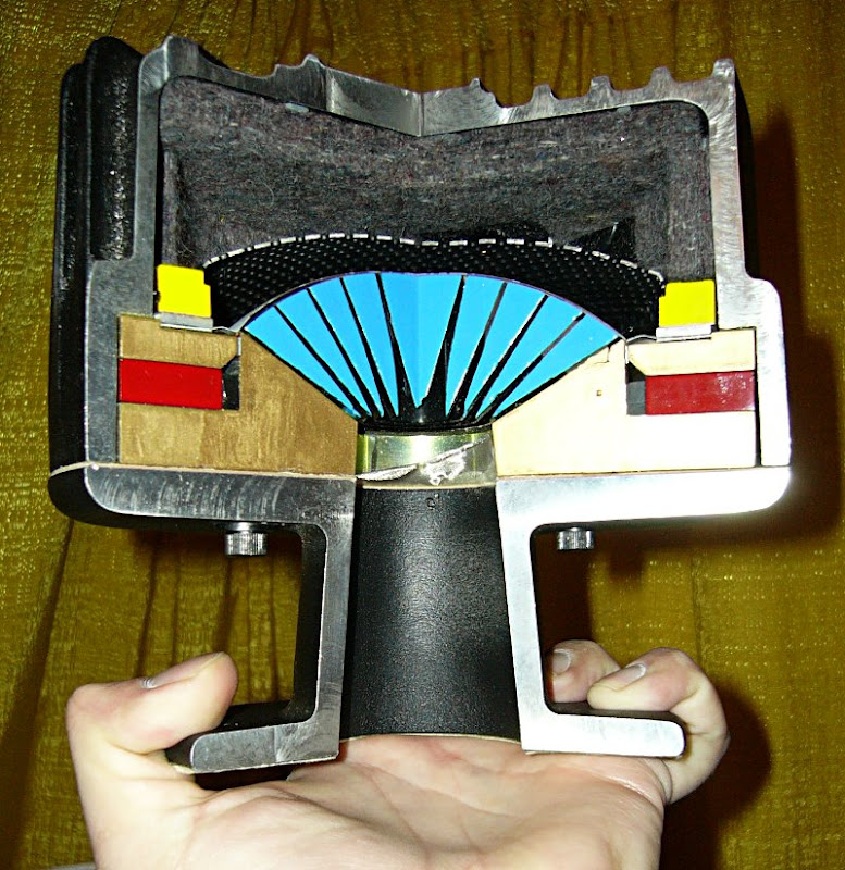
This is a TAD compression driver and it's phase plug. Pioneer has inverted the dome, which equalizes the pathlength.
Of course, this is a lot more difficult to manufacture.
I personally prefer the small compression drivers, for the reasons noted in the third or fourth post in this thread. I guess that a small diaphragm combined with a radial phase plug might be an excellent combination. I haven't seen a compression driver with a diaphragm as small as the Celestion which also uses a radial phase plugs. All of the small domed compression drivers that I'm aware of use relatively crude phase plugs.
Patrick, the blue and the red lines have the same starting and ending points. The blue is a straight line, and the red is broken in two sections to get around the narrowing. -->so the red is longer than the blue and more longer than the green. No need to measure anything? No?
I'd argue to simply measure it. Literally make a pic of it in Xara (it's free) and measure the pathlength.
The outside ring is a bigger surface (per degree of phase moving
in unison) than the middle.
I don't think you could sum to a complete cancellation, even if the
middle and edge reach a common manifold in complete opposition.
-----
If one were to build a paraline of a conventional 8" coax,
would it still be necessary to choke off the big cone to
a ring of small holes?
Last edited:
Correction
#2 - If we have two sources out of phase by or near 1/2 wavelength (180 deg.) .....
Regards,
WHG
The first thing we have to keep in mind, is basic quarter wave theory:
#1 - If we have two sources which are in phase, they will sum constructively as long as they're within about 1/4 wavelength
#2 - If we have two sources which are in phase, they will sum destructively (null each other out) when they're seperated by 180 degrees, or one-half wavelength
#2 - If we have two sources out of phase by or near 1/2 wavelength (180 deg.) .....
Regards,
WHG
- Status
- Not open for further replies.
- Home
- Loudspeakers
- Multi-Way
- :: An Illustrated Demonstration of the effect of Phase Plugs ::