@Mooly, does your simulation consider the actual dc resistances of the primary and secondary coils? or is an ideal transformer assumed?
The sim schematic does not show any resistances in series with the driving emf (V1). i.e. Rs=zero.
@Mooly, does your simulation consider the actual dc resistances of the primary and secondary coils? or is an ideal transformer assumed?
An ideal voltage source is assumed. I could add series impedance to the source that would mimick a load causing a voltage dip.
If there is doubt on the transformer then it might be worth measuring the actual voltages under load.
An ideal voltage source is assumed. I could add series impedance to the source that would mimick a load causing a voltage dip.
If there is doubt on the transformer then it might be worth measuring the actual voltages under load.
yes, i think actual load testing is in order....😀
The sim schematic does not show any resistances in series with the driving emf (V1). i.e. Rs=zero.
For a 100 ma load and a (supposed) 1.3 amp tranny there shouldn't be any issue. The regulation of the tranny probably puts the off/low load load volts considerably higher anyway.
As mentioned, if there is doubt over the tranny then at least do a few basic on/off load measurements.
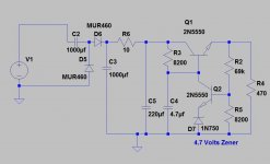
i make traffos the same size as what is shown in photo, an EI 66 has a center leg of about 3/4 inches....primary resistance is in the 200ohm+ range, secondaries in the 2ohm+ range....so that it is easy for the voltages to drop under load......
Could you insert an Rs and let us see the effect on output as Rs is varied from 0r0 to 100r (for a small transformer)
the 2 x 24volt windings are effectively in series....so that with 2 ohms series resistance and 200ohm primary winding resistance.......the effective secondary resistance is [200/(230/48)^2]+4 ohms, or about 12ohms....
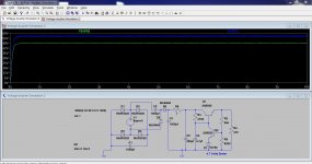
Well seems like I have to re-read all the postings again to make my silly brain understand it... I am trying to understand Mooly's simulation. Mooly, the Voltage Source in the diagram is 24V AC right?
Then how about the 12V regulated output? It should be taken from the other secondary with center-tap right? where It could be derived from? I dread discretes.. As it takes a while for me to understand the whole thing 😛
Then how about the 12V regulated output? It should be taken from the other secondary with center-tap right? where It could be derived from? I dread discretes.. As it takes a while for me to understand the whole thing 😛
Last edited:
Well seems like I have to re-read all the postings again to make my silly brain understand it... I am trying to understand Mooly's simulation. Mooly, the Voltage Source in the diagram is 24V AC right?
Then how about the 12V regulated output? It should be taken from the other secondary with center-tap right? where It could be derived from? I dread discretes.. As it takes a while for me to understand the whole thing 😛
24 volts AC yes. Thats why I put it at 33 volts 🙂 Confused 😀 Its because of the way voltages are specified in the simulation. Its the peak voltage not the RMS. 24 Vac gives around 34 volts dc after rectification and smoothing. I choose 33 rounding down.
The 12 volt regulated can still come from the other windings as you showed before.
Remember the two supplies are totally isolated and so you can connect the ground of the doubler circuit to the ground of the 12 volt supply.
Could you insert an Rs and let us see the effect on output as Rs is varied from 0r0 to 100r (for a small transformer)
Yes and no 🙂 My simulation skills haven't extended to stepping a variable like that yet. Fixed values I can manage.
Now 100 ohm is huge. 3 ohms was about as high as it would stand and allow a reasonable margin for the reg to work. I dropped the value of R6 too.
We have to put this in context though. Based on the spec of the transformer this should be a non issue. The secondary AC voltage shouldn't drop much when supplying a 100 ma load on the 48 volt rail.
If we have doubts about the transformer being up to snuff then its prudent to test it.
Attachments
@Mooly, That you very much for taking time to design and simulate something like this. You won't have a clue how much I appreciate your efforts for me.
Not forgetting @Tony, @RJM1 and @AndrewT. You guys rock!
I just wish someday, I could be at least half worthy of contributing to this forum like you guys...
And as for the circuit I think I will them build both and see how they behave in real life scenario.
No disrespect to Mooly but your circuit is more complex than something I would have liked to build, but nevertheless I will do it. But I am just thinking, how about I build the simple one first, load it up in my actual application scenario and see it works and if not go on to build the more complex but much elegant and robust one designed by Mooly? Just thinking aloud...
Last edited:
yes, you surely will learn more by actually doing it......good luck....😀
btw, i have a brother who is a PR in Singapore and lives in the Choa Chu Kang area, myself was in Singapore for 4 years working in the Jurong island Oils and Gas Projects....😀
btw, i have a brother who is a PR in Singapore and lives in the Choa Chu Kang area, myself was in Singapore for 4 years working in the Jurong island Oils and Gas Projects....😀
btw, i have a brother who is a PR in Singapore and lives in the Choa Chu Kang area, myself was in Singapore for 4 years working in the Jurong island Oils and Gas Projects....😀
Wow that's great! Is he in to Audio stuff as well? 🙂
- Status
- Not open for further replies.
- Home
- Amplifiers
- Power Supplies
- Fixed Linear Regulators a possibly stupid question