That’s almost right except you forgot the approximate 1V drop across the rectifiers.
Let’s start at the bottom (12Vac*1.414)=16.97V-1V= 15.97V at the input to the LM7812. The LM7812 minimum input voltage is 14.5V. So that should be fine.
With the bridge rectifier you have 2 diode drops and this will make the input voltage to your regulator (24Vac*1.414)=33.93-2=31.93+15.97=47.9V. Not enough to get 48V out even with a 0V dropout regulator.
can you post dc resistances of your traffo, primary and secondaries?
and can you define exactly your dc load requirements?
you mentioned 48volts at 100mA, so that is 4.8 watts, what about your 12volt rail?
once you know your loads, we can then look at your traffo and judge whether it is up to task....
For the 12V rail I approximately need 1A+ current.. Something like 15W maximum.
That’s almost right except you forgot the approximate 1V drop across the rectifiers.
Let’s start at the bottom (12Vac*1.414)=16.97V-1V= 15.97V at the input to the LM7812. The LM7812 minimum input voltage is 14.5V. So that should be fine.
With the bridge rectifier you have 2 diode drops and this will make the input voltage to your regulator (24Vac*1.414)=33.93-2=31.93+15.97=47.9V. Not enough to get 48V out even with a 0V dropout regulator.
I don't know whether the diodes will drop whole 1V across. considering this, I can select another zener 47V worst case... And end up with a 47-1.1V= Vz-Vbe=45.9V regulated, which should still do...
That’s almost right except you forgot the approximate 1V drop across the rectifiers.
Let’s start at the bottom (12Vac*1.414)=16.97V-1V= 15.97V at the input to the LM7812. The LM7812 minimum input voltage is 14.5V. So that should be fine.
With the bridge rectifier you have 2 diode drops and this will make the input voltage to your regulator (24Vac*1.414)=33.93-2=31.93+15.97=47.9V. Not enough to get 48V out even with a 0V dropout regulator.
make the bottom rectifier a 24v bridge also.....so then you will have about 64volts dc to the input of the 48v regulator...
use the center tap of the bottom rectifier winding to get 15.97volts to input of the lm7812....
my concern is the 12volt current draw...how big is it going to be?
Your calculations seems OK but they make me nervous 🙂 Seeing high voltage zeners and low value resistors... there's no "compliance" or overhead.
I'm not trying to find fault, its just that I wouldn't do it that way 🙂
You could arrange a voltage doubler from the 24 volt winding. That would give nearer 60 to 65 volts volts DC in its own right. That could then be referenced to the main 12 volt ground.
I think it could also be done by series connecting the 24 volt winding to the 12 volts and using an AC coupling/diode/AC coupling etc arrangement to produce the high voltage rail. I'd need the transformer to play with though to come up with that scheme.
Well that's too much for my booze decayed brain to think through... I would really need some help then 🙂
make the bottom rectifier a 24 bridge also.....so then you will have about 64volts dc to the input of the 48v regulator...
use the center tap of the bottom rectifier winding to get 15.97volts to input of the lm7812....
my concern is the 12volt current draw...how big is it going to be?
12V current draw need is approx 1A. That is the only thing that requires some real current.
so 12watts and 4.8 watts makes 16.8 watts....you may actually need a 20watt traffo...
can you post core dimensions of your traffo?
can you post core dimensions of your traffo?
make the bottom rectifier a 24v bridge also.....so then you will have about 64volts dc to the input of the 48v regulator...
use the center tap of the bottom rectifier winding to get 15.97volts to input of the lm7812....
my concern is the 12volt current draw...how big is it going to be?
If the lower rectifier also go for fullwave-bridge then how will I reference to the ground? put a single diode on the center tap too? because for the bridge rectifier -ve is going to be the ground then. So that means center tap is still non-rectified AC. Am I correct?
so 12watts and 4.8 watts makes 16.8 watts....you may actually need a 20watt traffo...
can you post core dimensions of your traffo?
Transformers picture is posted above in the thread.
Here is it again
An externally hosted image should be here but it was not working when we last tested it.
If the lower rectifier also go for fullwave-bridge then how will I reference to the ground? put a single diode on the center tap too? because for the bridge rectifier -ve is going to be the ground then. So that means center tap is still non-rectified AC. Am I correct?
no, the center tap will have a dc voltage half of the full bridge output wrt to ground point or neg. point.......you can use it to input to your lm7812 regulator....for this, choose the winding that has lower dc resistance from the 2 coils on your secondary...
no, the center tap will have a dc voltage half of the full bridge output wrt to ground point or neg. point.......you can use it to input to your lm7812 regulator....for this, choose the winding that has lower dc resistance from the 2 coils on your secondary...
Wow that's something I can't visualize/comprehend... May be I need to go back and read my old electrical text books from the school again. 🙂 May be I should wire it up and check also...
you can wire it up and see for yourself.....you can refresh your memories here: http://www.hammondmfg.com/pdf/5c007.pdf
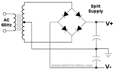
this is a full wave bridge with center tap, if you move your zero ground the the V- then the center tap and the junction of the two caps becomes 1/2(V+ - V-)....
this is a full wave bridge with center tap, if you move your zero ground the the V- then the center tap and the junction of the two caps becomes 1/2(V+ - V-)....
you can wire it up and see for yourself.....you can refresh your memories here: http://www.hammondmfg.com/pdf/5c007.pdf
this is a full wave bridge with center tap, if you move your zero ground the the V- then the center tap and the junction of the two caps becomes 1/2(V+ - V-)....
Yeah for sometime, I couldn't really visualize it that way. Thanks for the above diagram. Now only one question. What you really see here in a way is a voltage doubler isn't it? by the caps? So a single cap across the lower ground(V- in the picture) and V+ wouldn't just do right?
I still have to use two caps between the center tap one on each side and then add the V+ to the upper (other secondary's) -ve to come up with a whole 66VDC+ right?
After taking Tony's and RJM1's input this is the revision I came up with...
An externally hosted image should be here but it was not working when we last tested it.
Yeah for sometime, I couldn't really visualize it that way. Thanks for the above diagram. Now only one question. What you really see here in a way is a voltage doubler isn't it? by the caps? So a single cap across the lower ground(V- in the picture) and V+ wouldn't just do right?
I still have to use two caps between the center tap one on each side and then add the V+ to the upper (other secondary's) -ve to come up with a whole 66VDC+ right?
your scheme as drawn is just right......

don't be too concerned about the high b+ it will drop like a stone under load...😀
No,If we discard the center tap and go for 24V the current capability goes down by half right? (
The current capability stays the same.
Each winding has a maximum (continuous) Imax. That does not change.
Not really. No voltage is being doubled, all that's being done is relabeling the outputs. Am I correct that each secondary is rated 1.3A? A possibility would be to use a voltage doubler at one 24V 1.3A secondary (for line level) and a second paralleled secondary at 12V 2.6A for power amp).What you really see here in a way is a voltage doubler isn't it?
Well that's too much for my booze decayed brain to think through... I would really need some help then 🙂
Its hard for me to visualise without having the real part to play with.
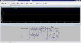
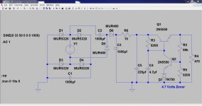
This is a doubler idea taken from a simulation I did for another project but it shows the general idea. Forget the transistor type, its not suitable but they don't smoke in LTspice 🙂
Attachments
the traffo is made in china so i am not confident that it can deliver the loads as required...the thing to do is to test it under load.....
load the 48v rail with a 470ohm 5watt resistor
and the 12volt rail with a 12ohm 25watt resistor.....
only then can we verify that the traffo is adequate....
if voltages hold up under simultaneous load, and if the traffo does not smoke, then the psu is confirmed...
load the 48v rail with a 470ohm 5watt resistor
and the 12volt rail with a 12ohm 25watt resistor.....
only then can we verify that the traffo is adequate....
if voltages hold up under simultaneous load, and if the traffo does not smoke, then the psu is confirmed...
Hope that makes sense. The green trace is the stabilised 48 volt line. The red trace is the rectified 24 volts AC (approx 33 vdc) and the blue trace is the doubler output.
Now I'm sure it can be done even more elegantly by cascading the windings in series and using the cap/diode/cap arrangement but I can't do it in my head 🙂
Now I'm sure it can be done even more elegantly by cascading the windings in series and using the cap/diode/cap arrangement but I can't do it in my head 🙂
- Status
- Not open for further replies.
- Home
- Amplifiers
- Power Supplies
- Fixed Linear Regulators a possibly stupid question