John - I just watched your video clip. Very interesting. What sort of horn are you intending to add? This is definitely on my to do list now - I've just got some 5mm plywood to start experimenting with. I need to find some cheap drivers here in Hong Kong now.
Tom,Hi Art
The TAD drivers are a bit unusual in that they generally have a very low (for a compression driver) resonant frequency and so the traditional series cap leaves them fully un-damped and easy for the diaphragm to move around.
What works much better is a driver with a higher Fs and more excursion capability and then using a parallel choke as the final element across the driver. This way instead of seeing an open circuit as the frequency falls, it sees a short and is highly damped and very hard for external pressure to move around.
I try to use that L as the majority of the compensation slope involved so they are typically a fairly small value as well. In some cases, the L is small enough to make the compression drivers impedance a non-issue as well as it dominates the crossover load..
Has it been unusually hot and dry in your neck of the woods (or desert) this year (like it has been here)?
The only upside is very few mosquitoes.
Best,
Tom
Good crossover tips.
Just took a trailer trip up to Minnesota where the mosquito is the state bird and did not get a single bite there or anywhere further east all the way to Pennsylvania. There seem to be some pockets of wet areas but a lot of brown corn, food prices will be going up.
It has been super dry here except for a few gully-washers. My well is only producing slightly more water than we need, if things get any worse will have to co-ordinate clothes washing with my two neighbors who I provide water for...
Are any of your current designs using mid and high drivers on the same Paraline?
Art
John - I just watched your video clip. Very interesting. What sort of horn are you intending to add? This is definitely on my to do list now - I've just got some 5mm plywood to start experimenting with. I need to find some cheap drivers here in Hong Kong now.
A simple wave guide bent at 90 degrees that has a 2" X 16" mouth. This paraline is going into my friend's show car. They will be mounted under the dash. These were to be just proof of concept. I'm completely satisfied that having the mids on the paraline is feasible, practical and quite desirable. The next ones I build will be for home Hi-Fi. Those will be a much more serious and exacting design than the current ones.
All the examples shown here seem to be for drivers with sealed backs. Are there any reasons that this could not be applied to an open-backed driver like a HiVi B3 or old paper coned tweeter?
All the examples shown here seem to be for drivers with sealed backs. Are there any reasons that this could not be applied to an open-backed driver like a HiVi B3 or old paper coned tweeter?
You can do U-Frames, H-Frames, back loaded horns and tapped horns with a Paraline. It just depends on where you put the back wave.
I am particularly interested in something like a W-Horn. Basically you modify the mouth of the Paraline, and leave a gap so that the woofer can sit in the mouth. This has some neat advantages:
- The Paraline rolls off the highs. By putting the woofer outside of the line, you could potentially do a full range Paraline, similar to the Fostex boxes sold by Madisound. (Basically, you're never going to have a single driver Paraline with a sealed rear chamber, because the Paraline rolls the highs off too much. The only way you're going to get full range with a sealed rear chamber is if you have a compression driver *and* some midranges in there, like the Paralines that John and I have posted videos of.)
- One of the reasons that a tapped horn has limited bandwidth is that you get a ton of comb filtering. For instance, with a tapped horn that's tuned to 80hz, you'll get a deep notch at 240hz if my memory is correct. But with a W-Horn Paraline, you can adjust the height of the Paraline to filter out the highs. If you do this carefully, you could likely get something close to full range performance out of one driver.
Again, all the same rules apply as any other horn. The Paraline isn't a new type of horn, it's just a new folding scheme. You can easily do back loaded horns with it.
I posted some pics of a NEO8 Paraline Dipole I did.
Patrick Bateman,
I don't see any reason that what you are proposing wouldn't work. That looks an awful lot like some old RCA W-cabinets that I had to move around when I was much younger....
What I do see is if you married a bass horn like this with a Paraline you would need to include an electronic time alignment correction factor due to the extreme difference in length of the signal paths.
Hello John,A simple wave guide bent at 90 degrees that has a 2" X 16" mouth. This paraline is going into my friend's show car. They will be mounted under the dash. These were to be just proof of concept. I'm completely satisfied that having the mids on the paraline is feasible, practical and quite desirable. The next ones I build will be for home Hi-Fi. Those will be a much more serious and exacting design than the current ones.
If you don't mind me asking is the plan to physically aim the horns for crossfiring? Fire straight ahead or use some of the techniques Patrick had mentioned to shape the wavefront? I'm still trying to grasp how to do that... Or maybe it's just a one seater using digital time alignment?
Sorry all the questions were in reference to the car. I know it's just a proof of concept, but it sounds great. (the horn and the car idea. )
Last edited:
So I've been reading, studying, and thinking trying to figure this out. I've got some ideas but none of them seem to hold up in all aspects.....
So how do we determine the size of the paraline? Earlier in the thread there was talk of sizing the radius to a 1/4 wl of the lowest freq we want to produce. 1/4 wl of 300hz is about 11", and from your pics the radius of your paraline looks to be about 5"? Does the horn the paraline attaches to determine the lower cutoff, rather than the radius of the paraline? I'd guess we use the radius to determine the vertical window.........
I'm thinking about taking advantage of the long weekend coming up and getting some paralines built, but I'm not yet sure how to size it properly. FWIW I'm going to be using the 4" closed back Celestions (got a box coming so I'll make several driver mounting plates and play around) down to 250hz on a 60x40 conical with the little BMS 4524 CD.
I'm looking to run the RDC3TA from 300Hz to about 1.9KHz.
So how do we determine the size of the paraline? Earlier in the thread there was talk of sizing the radius to a 1/4 wl of the lowest freq we want to produce. 1/4 wl of 300hz is about 11", and from your pics the radius of your paraline looks to be about 5"? Does the horn the paraline attaches to determine the lower cutoff, rather than the radius of the paraline? I'd guess we use the radius to determine the vertical window.........
I'm thinking about taking advantage of the long weekend coming up and getting some paralines built, but I'm not yet sure how to size it properly. FWIW I'm going to be using the 4" closed back Celestions (got a box coming so I'll make several driver mounting plates and play around) down to 250hz on a 60x40 conical with the little BMS 4524 CD.
Needs to learn more so I can do a paraline on the rear deck of my car for some larger midbasses...put the edge of the paraline all the way out to the edge of the interior of the car so they aren't straight behind the head.
So I've been reading, studying, and thinking trying to figure this out. I've got some ideas but none of them seem to hold up in all aspects.....
So how do we determine the size of the paraline? Earlier in the thread there was talk of sizing the radius to a 1/4 wl of the lowest freq we want to produce. 1/4 wl of 300hz is about 11", and from your pics the radius of your paraline looks to be about 5"? Does the horn the paraline attaches to determine the lower cutoff, rather than the radius of the paraline? I'd guess we use the radius to determine the vertical window.........
I'm thinking about taking advantage of the long weekend coming up and getting some paralines built, but I'm not yet sure how to size it properly. FWIW I'm going to be using the 4" closed back Celestions (got a box coming so I'll make several driver mounting plates and play around) down to 250hz on a 60x40 conical with the little BMS 4524 CD.
Hornresp can get you in the ballpark. The wave expands radially. So the area of the horn throat is equal to the mouth of the compression driver. And then the mouth area depends on how far away you are from the throat. For instance, if you are 40cm away from the throat, the area is (2 * 3.14159 * 40cm * 0.635) or 159.59. (this assumes an internal height of 0.635)
Yes, the Paraline is eye-shaped, but the sound expands in rings.
Also, these things are so easy to build, you might just skip Hornresp and head straight to the garage. I can build a Paraline in under an hour.
If you skip Hornresp, just remember the quarter wave resonance will be equal to the speed of sound divided by the height of the Paraline divided by two.
Thanks, but I guess I should rephrase my question. I understand how to calculate the size of the paraline for the 1/4 wl of the lowest freq. I also understand how to calculate the mouth opening.
JLH's paraline looks to be about 10-11" tall, so that's about a 5" radius which figures out to about 600hz. He stated he wanted to use it down to about 300hz. This goes against the math, as a 300hz paraline would be about 22" tall. Does the "traditional" conical horn that the paraline's mouth attaches to determine the lower extension? I don't mind building a 22" tall paraline, but if it can be done with a 10" paraline then that's even better.
JLH's paraline looks to be about 10-11" tall, so that's about a 5" radius which figures out to about 600hz. He stated he wanted to use it down to about 300hz. This goes against the math, as a 300hz paraline would be about 22" tall. Does the "traditional" conical horn that the paraline's mouth attaches to determine the lower extension? I don't mind building a 22" tall paraline, but if it can be done with a 10" paraline then that's even better.
Last edited:
Thanks, but I guess I should rephrase my question. I understand how to calculate the size of the paraline for the 1/4 wl of the lowest freq. I also understand how to calculate the mouth opening.
JLH's paraline looks to be about 10-11" tall, so that's about a 5" radius which figures out to about 600hz. He stated he wanted to use it down to about 300hz. This goes against the math, as a 300hz paraline would be about 22" tall. Does the "traditional" conical horn that the paraline's mouth attaches to determine the lower extension? I don't mind building a 22" tall paraline, but if it can be done with a 10" paraline then that's even better.
The Paraline is simply the first segment in a larger horn. In this VTC Box the horn cutoff is dictated by the width depth and height of the horn mouth.
In a car you can use a corner to mimimic the effect of having a much larger horn. Basically jam the Paraline in a corner and let the corner load your horn.
I sized the paraline to accommodate the mounting of the mid ranges. The ratio of height to width determine the horizontal dispersion. Since these are going into a car, I opted for a pretty narrow dispersion angle resulting in a wider eye.
The mouth size and horn length do impact the low cutoff of the horn. However, the local area of expansion (aka the flair rate the mids see) dictates how low the mids will play. This is touched on in the Synergy horn white paper on the Danley website. It is also explained in more detail in the Synergy patent. Look at page 9 and 10 in the patent.
The mouth size and horn length do impact the low cutoff of the horn. However, the local area of expansion (aka the flair rate the mids see) dictates how low the mids will play. This is touched on in the Synergy horn white paper on the Danley website. It is also explained in more detail in the Synergy patent. Look at page 9 and 10 in the patent.
This is touched on in the Synergy horn white paper on the Danley website. It is also explained in more detail in the Synergy patent. Look at page 9 and 10 in the patent.
Thanks, things make more sense now after reading that and realizing my confusion. Earlier in the thread there was talk of sizing the paraline to 1/4 wl of the lower cutoff freq, for a paraline sub that would be playing on its own, not mounted to another horn segment. I couldn't figure out why the paraline itself had to be sized for the lower cutoff freq - because it doesn't! Duh.
Another thing that's been on my mind is how the mids enter the paraline. On a Synergy horn one of the benefits of the way the mids enter the horn is the shape and size of the ports, creating the acoustic low-pass filter and reducing distortion accordingly. Is this something we could take advantage of with a paraline as well, or are we trading that for the extended upper bandwidth we get from the mids?
This stuff looks way cool, and looks easy enough to build that I'd like to try. I've got alot of reading to do to catch up though. Hopefully it'll still be cool when I try it, not like that time that I was a year late in getting a Razor phone. 😛
... On a Synergy horn one of the benefits of the way the mids enter the horn is the shape and size of the ports, creating the acoustic low-pass filter and reducing distortion accordingly. Is this something we could take advantage of with a paraline as well, or are we trading that for the extended upper bandwidth we get from the mids?
You can do that with Paraline-mounted mids. The Paraline patent shows this in its example of adding mids to a Paraline.
This stuff looks way cool, and looks easy enough to build that I'd like to try. I've got alot of reading to do to catch up though. Hopefully it'll still be cool when I try it, not like that time that I was a year late in getting a Razor phone. 😛
These things are so easy to build, I say just dive in and make one. No need to make this too complex. If you can live with a flat wavefront, then cut five pieces of wood and make each piece twice as tall as it is wide. Draw the 'eye' by hand. Array the driver(s) around the center. Make the mouth about 2cm wide, and as tall as the long end of your wood.
Boom! You got a Paraline.
Humor me and post videos of it plz 🙂
You can do that with Paraline-mounted mids. The Paraline patent shows this in its example of adding mids to a Paraline.
Yeah I see that, though he just says that they can be added and there's the drawing showing the 2-port/driver config. He doesn't say that the port improvements from the synergy patent could be applied here, but that won't stop me from trying 😉
I'm just wondering if there's any aspect of the paraline design itself that would prohibit this that's not obvious to me.
...
1. Take the eye-shaped configuration that's in the Paraline patent
2. Move the ENTRANCE off center by one inch
3. Move the EXIT off center by one inch
4. As long as the the change is balanced, path lengths stay equal. For instance, move the horn exit to the left by 1" and the horn entrance to the right by 1". Path length is same.
5. As Don noted, the tweeter fires THROUGH the center plate.
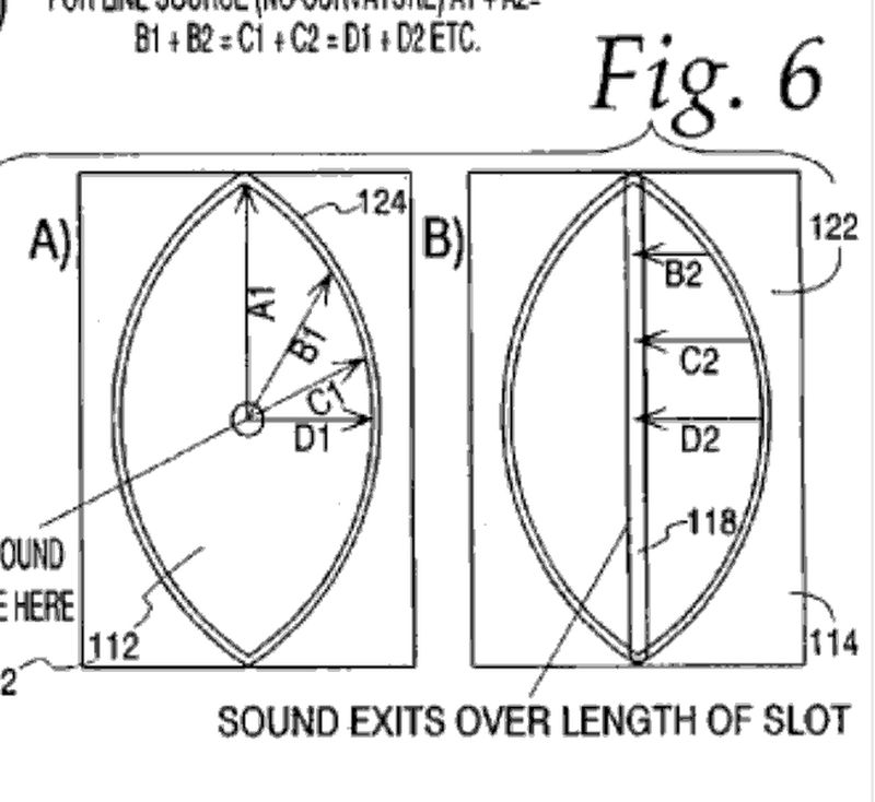
The eye shape ends up looking a little droopy, bcuz the widest point of the Paraline (aka A1) moves along with the entrance.
Just thinking... instead of curving the mouth, curve the eye-shaped slot. That is, alter the shape of the slot profile to keep the path lengths equal while keeping the mouth straight.
Just thinking... instead of curving the mouth, curve the eye-shaped slot. That is, alter the shape of the slot profile to keep the path lengths equal while keeping the mouth straight.
Don - I was thinking the exact same a couple of weeks ago. You end up with an asymmetrical eye that looks more like a horizontally-stretched 'D' (on both sides).
- Home
- Loudspeakers
- Multi-Way
- Square Pegs