Its not steady to rely on such a small VR1 margin. Heat up cycle can disrupt it. Better bodge a 4th led to widen that voltage and use a higher value R1. Or stick a blue led in the now gang of 3. Better aim at 0.7A also.
That's a void question if you will not decide the new leds scheme and estimate the voltage margin first. Use the Excel calc.
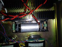
Vref Red LED again burned!
Surely burned, or went out due to no current left for it bcs all gone to heavy load?
Now is OK 5Vout with 10R3 dummy load
Voltage across R1 3R3 2.1V 636mA
Why when Trig LED in the scope lits the line in the scope blinks?
Voltage across R1 3R3 2.1V 636mA
Why when Trig LED in the scope lits the line in the scope blinks?
Why when Trig LED in the scope lits the line in the scope blinks?
Because it likely tries to trigger on nothing in particular. Depends on your scope and on your trigger setting.
A Salas type regulator is bombproof.
I have explained before that one can leave the output open circuit and the regulator should not fail if designed correctly.
I have explained before that one can short circuit the output and the regulator should not fail if designed correctly.
I have stated that the heatsinking and the Main mosFET devices should be chosen to survive the worst case loadings. These are:
a.) For the CCS mosFET:- Short circuit output and maximum mains voltage.
b.) For the Shunt mosFET:- open circuit output.
These two worst case conditions cannot co-exist. Therefore some saving in heatsinking can be obtained by sharing a heatsink between the CCS & Shunt mosFETs. Again I have posted this in the past.
If you having failing components then you have designed the modified version in correctly.
He effectively tested a. with 6R8 dummy in his setting yesterday and it survived. Having a failed BC550C he discovered, there are no likely dissipation reasons for the error amp function it serves especially at such low Vo.
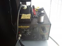
Maybe persistent with a slow recovery iron weakening some parts during initial construction? Even if not, its a very good idea to use a station in general and not a mains iron. XYTRONIC LF-1600 I see in US, UK, and DE stores, Hakko FX-888 in US is a bargain, elsewhere its a rip-off or a clone, etc. But many affordable choices to get a station guys, really. Just set it at 350C and use eutectic leaded solder. A mains iron and ROHS solder is manipulating joints too heavily.
For the record, the v1.1 I had built for my EVO shows no signs of oscillation on a Fluke 20MHz ScopeMeter.
While testing, I accidentally shorted S+ and 0 (twice!) and both the regulator and the load recovered as soon as the short was lifted. No damage whatsoever.
While testing, I accidentally shorted S+ and 0 (twice!) and both the regulator and the load recovered as soon as the short was lifted. No damage whatsoever.
Draw or print a BIG version of the schematic.
Mark on all the component values.
Mark on the input and output voltages.
Calculate the current through every component.
Calculate the voltage at every end of every component.
Add these currents and voltages to your BIG schematic.
Now look at the schematic and check that all your additions make sense.
If you are not sure, then post a pic of your BIG marked up schematic here.
How can increase Vout to 5,25V and current to minimum 800mA or more?
Does the huge capacitor allow the BC550C & Leds underneath to breath? Adding 0.25V its a matter you find the current you run in your Vref now and add a bit of resistance value to reach it. 2R7 R1 or bit less can boost your CCS higher. That's all in the calc, practice it.
- Home
- Amplifiers
- Power Supplies
- SSLV1.1 builds & fairy tales