hi apex sir,
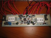
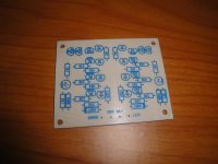
this is testing purpose with wired.
my apex vu meter.
pls help, check my last posts.
this is testing purpose with wired.
my apex vu meter.
pls help, check my last posts.
Attachments

beginner´s advice
Is there other resistor in series with that 10k pot? If there is try to put another with lower resistance but be careful-do it with all safety mesures. I am just a beginner and that was something i would do if i was in your place. Safety first so you don´t lose any transistors.
hi apex sir pls help,
tef is working,
i adjust the 10k pot to 2vdc with 10r/10w resistor in rail.
below 2vdc cant adjust because 10k pot is minimum clockwise, if i turn to anticlockwise dc v is increasing, so how can i decrease dcv ? pls reply to this.
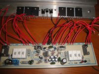
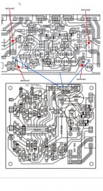
the bias transistor is bd681 not mje340.
in the image shows mje340.
Is there other resistor in series with that 10k pot? If there is try to put another with lower resistance but be careful-do it with all safety mesures. I am just a beginner and that was something i would do if i was in your place. Safety first so you don´t lose any transistors.
hi apex sir pls help,
tef is working,
i adjust the 10k pot to 2vdc with 10r/10w resistor in rail.
below 2vdc cant adjust because 10k pot is minimum clockwise, if i turn to anticlockwise dc v is increasing, so how can i decrease dcv ? pls reply to this.
the bias transistor is bd681 not mje340.
in the image shows mje340.
Replace 15k resistor with 10k in bias circuit (from colector to base of BD681)
hi apex sir, thanks for the reply.
now i can adjust .5v to up.
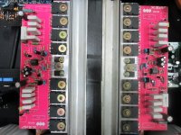
i supplied 45dcv with 2pair output.
i adjust 1dcv for bias with 10 ohm resistor instead fuse. heatsink is getting little hot after 10 minutes.
can u tell me what is the bias voltage for 8pairs output.
now i can adjust .5v to up.
i supplied 45dcv with 2pair output.
i adjust 1dcv for bias with 10 ohm resistor instead fuse. heatsink is getting little hot after 10 minutes.
can u tell me what is the bias voltage for 8pairs output.
hi apex sir, thanks for the reply.
now i can adjust .5v to up.
i supplied 45dcv with 2pair output.
i adjust 1dcv for bias with 10 ohm resistor instead fuse. heatsink is getting little hot after 10 minutes.
can u tell me what is the bias voltage for 8pairs output.
Set 20mA per pair of output.
hi apex sir, thanks for the reply.
could u tell me how many dcv from 10 ohm resistor instead fuses for 20ma per pair.
can i supply 90vdc to to work with 8pairs?
could u tell me how many dcv from 10 ohm resistor instead fuses for 20ma per pair.
can i supply 90vdc to to work with 8pairs?
hi apex sir, thanks for the reply.
could u tell me how many dcv from 10 ohm resistor instead fuses for 20ma per pair.
can i supply 90vdc to to work with 8pairs?
Set 2V on 10R, and use large heatsink with fan.
hi apex sir, thanks for the reply.
for testing purpose i adjust bias with .5dcv in 10 ohm resistor and checked,with two pair the sound is excellent and heat is less.
thanks sir for the help.
for testing purpose i adjust bias with .5dcv in 10 ohm resistor and checked,with two pair the sound is excellent and heat is less.
thanks sir for the help.
hi apex sir,
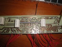
if i remove these resistors and zeners ,and provide supply from protect board 15vdc, is it works? any other parts to replace?
because the voltage is changing morning and evening time, (in my home and my shop.)
so no need to change ic resistor r23 and r24.
if i remove these resistors and zeners ,and provide supply from protect board 15vdc, is it works? any other parts to replace?
because the voltage is changing morning and evening time, (in my home and my shop.)
so no need to change ic resistor r23 and r24.
Attachments
Hello anybody this circuit is working? How about the protect where can i connect this? How much the maximum ampere of this circuit. Thanks
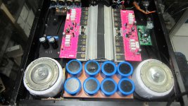
After I made the final version of the toshiba one pair and I tried to make the original version of the APEX B500 with each PSU, I use a transformer Toroit 7 Amperes at 40AC, I measure the MMD in the speaker output of about 0.3 VDC. Apex I hope you can guide me. Thank you. Damanhuri
Attachments
This amp working well? No hum?
This power works well and there is no hissing sound, I'm happy with the mid vocals, and a solid low.
- Home
- Amplifiers
- Solid State
- 500W PA amplifier with Limiter