does it work now?
No Bias is not stable and is increasing
Q8 and Q9 are getting hot but remaining transistors are cool even played at low volume
why those transistors are getting hotter than Q11,Q12,Q13,Q14??
Last edited:
No Bias is not stable and is increasing
Q8 and Q9 are getting hot but remaining transistors are cool even played at low volume
why those transistors are getting hotter than Q11,Q12,Q13,Q14??
could you post a picture or two? maybe you are overseeing something...
could you post a picture or two? maybe you are overseeing something...
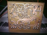
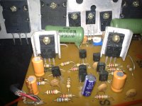
These are the pictures
Attachments
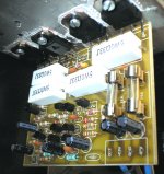
Did you switched places for IN input and SG signal-groud wires,or is it me? Do you have any dc-offset?
Did you switched places for IN input and SG signal-groud wires,or is it me? Do you have any dc-offset?
No
DC offset is about 34mV and is not stable
Attachments

Last edited:
Are you aware that BC and 2N transistors have different pinouts? They are inverted one from the other (CBE x EBC).
I made this amplifier for test my home DIY speakers (two way TL).
which is the maximum voltage for use with 8 "ohms"?
Are you aware that BC and 2N transistors have different pinouts? They are inverted one from the other (CBE x EBC).
You can see the picture they were inserted properly
Attachments

Hi! Mile could you please help me regarding dc offset problem
Hi! Mile
Please read this post
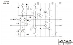
Hi Apex i am new in diyaudio,I want to build your amplifier in post #144 AX100 please post schematic diagram and what is the minimum and maximum rail voltage of this desing kindly help me.Sorry for my bad English, Thanks in advance
I will post those files for you tomorrow,now i am on my mobile. There will be a schematic,pcb and layout.
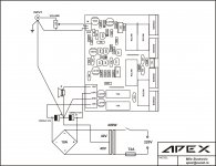
Here vou are...
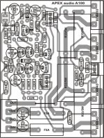
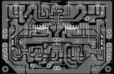
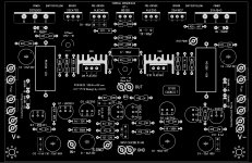
These would be the files needed:
Hi Apex i am new in diyaudio,I want to build your amplifier in post #144 AX100 please post schematic diagram and what is the minimum and maximum rail voltage of this desing kindly help me.Sorry for my bad English, Thanks in advance
These would be the files needed:
Attachments

Last edited:
thank you sir, now i can start building my apex amp AX100,,,Sorry for my bad English
Regards to all
Regards to all
and sir what is tha max. rail voltage of this circuit using 2 pair of tip142/147 thanks a lot for the quick reply sir, regards
and sir what is tha max. rail voltage of this circuit using 2 pair of tip142/147 thanks a lot for the quick reply sir, regards
+/-45V is max.
Components Replaced?
Dear sir Apex and other members!
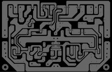
I'm a new audio diyer. After long time read many shematic at here, I decided to build AX-17V2. But in my country (Vietnam), 2N5401 and 2N5551 is hard to find and fake. I can replaced 2N5401 & 2N5551 by BC550 - BC560 or 2SC1815/2SA1015 ? I can get BC550/BC560 & 2SC1815/2SA1015 more easy. I redraw PCB that I downloaded from here, because copper in my PCB I gotten is thin, it can break when I replaced components... It is correct? I redraw a version for diffirence pins of 2SA1015/2SA1815 later.. Thanks for all!
Dear sir Apex and other members!
I'm a new audio diyer. After long time read many shematic at here, I decided to build AX-17V2. But in my country (Vietnam), 2N5401 and 2N5551 is hard to find and fake. I can replaced 2N5401 & 2N5551 by BC550 - BC560 or 2SC1815/2SA1015 ? I can get BC550/BC560 & 2SC1815/2SA1015 more easy. I redraw PCB that I downloaded from here, because copper in my PCB I gotten is thin, it can break when I replaced components... It is correct? I redraw a version for diffirence pins of 2SA1015/2SA1815 later.. Thanks for all!
Attachments
Dear sir Apex and other members!
I'm a new audio diyer. After long time read many shematic at here, I decided to build AX-17V2. But in my country (Vietnam), 2N5401 and 2N5551 is hard to find and fake. I can replaced 2N5401 & 2N5551 by BC550 - BC560 or 2SC1815/2SA1015 ? I can get BC550/BC560 & 2SC1815/2SA1015 more easy. I redraw PCB that I downloaded from here, because copper in my PCB I gotten is thin, it can break when I replaced components... It is correct? I redraw a version for diffirence pins of 2SA1015/2SA1815 later.. Thanks for all!
Nice pcb, use 2SA970 and 2SC2240 instead 2N5401 and 2N5551.
viktor1986 has noticed a mistake in a pcb-design: the base of the 2SC5200 is connected to a base 2SC4793,instead to it´s emitor. The lines to B and E of 2SC4793 have switched places,that should be changed.
That is what i have noticed after viktor´s warning,maybe he has seen something more,i don´t know. As far as i have seen that would be the only mistake done here...
That is what i have noticed after viktor´s warning,maybe he has seen something more,i don´t know. As far as i have seen that would be the only mistake done here...
- Home
- Amplifiers
- Solid State
- 100W Ultimate Fidelity Amplifier