When doing crossover calculation, does inductance of speaker has to be taken into account? Like, calculation says 2.5mH coil, but as iductance of voice coil is already 1mH, do I deduct it from calculation and make 1.5mH coil...
When doing crossover calculation, does inductance of speaker has to be taken into account? Like, calculation says 2.5mH coil, but as iductance of voice coil is already 1mH, do I deduct it from calculation and make 1.5mH coil...
No, you don't deduct the inductance like that.
When you design a crossover, you need driver's parameters as input. The effects of voice coil are already included in those parameters. For example, how come a woofer produce more bass and less treble if the voice coil has not been taken into account. You can see also from impedance chart (which raises with frequency) the effect of this voice coil.
You CAN flatten the impedance (at higher frequency caused by voice coil) by adding external crossover component called a zobel.
I forget tho, what are the "minimum" parameters required in a simplest crossover calculator that you might have concern with, as good speakers are not designed with such a minimal data and tool.
But even in the simplest online calculator, ime, the coil inductance is not directly considered (but the impedance), so the resulting coil calculated is for the external part without having to be substracted with voice coil inductance (Le).
Thanks Jay,
Perhaps there was a missunderstanding; I know that in crossover calculator it is IMPEDANCE that is used to calculate the coil. But once the coil is calculated, isn't it benefitial to reduce the calculated inductance (say again 2.5mH) by the amount of voice coil inductance? After all, the new inductor and the voice coil are now TWO inductors in the path of audio signal, and their inductances are now adding up...
You'd always design a speaker using a simulator like Visaton's Boxsim in practise. But yes, your initial guesses as to where you want to go take into account voicecoil inductance.
This sort of thing is really not going to work in practise, though tweeter values are sometimes about right, the bass will be far different:
This little speaker is a wallmounted bookshelf, so needs no bafflestep correction. Hence the input coil is set at exactly the voicecoil inductance of the W130S bass unit. 0.6mH. It all works out nicely to give you a third order butterworth on bass and treble. The "Invisible" coil is the bass unit itself. The bass capacitor is not far off twice the Zobel capacitor value either. 😎
This sort of thing is really not going to work in practise, though tweeter values are sometimes about right, the bass will be far different:
An externally hosted image should be here but it was not working when we last tested it.
This little speaker is a wallmounted bookshelf, so needs no bafflestep correction. Hence the input coil is set at exactly the voicecoil inductance of the W130S bass unit. 0.6mH. It all works out nicely to give you a third order butterworth on bass and treble. The "Invisible" coil is the bass unit itself. The bass capacitor is not far off twice the Zobel capacitor value either. 😎
Attachments
Thanks Steve, nice and clean drawing, and Visaton software looks good too. Still I haven't got answer to my question: if a circuit configuration can be used which has a series inductance in the low frequency output (like woofer), can the part of that inductance be voice coil. In other words, if Visaton calculator gives value of 1mH for LF filter inductor at particular frequency, and voice coil inductor is 0.5mH, is it correct to reduce filter inductor to 0.5mH, to achieve required 1mH. That would maintain constant resistance property of the filter, in my view. If not, why not...
The answer is no. The response at a given frequency is in proportion to the voltage across the voice coil. The voice coil impedance and resistance are an integral part of the coil. The inductor creates a voltage divider with the voice coil.
There is a pattern where the voicecoil inductance plays a part in the final filter. Look at this KEF 104ab which uses the B200 SP1039, which is Le=0.25 mH:
When KEF worked with the B200 SP1054, which is Le=0.45 mH, well they found they could skip the second coil altogether. Not exact, but the pattern is there.
What you can say for sure, is that woofers with bigger Voicecoil inductance will often need bigger filter components for the same crossover. In fact bigger Le usually also means a lower crossover point in practise.
If you want the formula, Le/Re squared = Zobel capacitance.
So for your 6 ohm, 1mH woofer, you'll be looking at capacitors around, er, 1000/36= 27uF somewhere. I don't like woofers with that high an inductance for a crossover around 3kHz. They fight you all the way unless you use huge coils. 😀
Oh, FWIW, and Lynn Olson pointed this out, voicecoil inductance is not really like a regular coil. It's very non-linear and lossy and you have to fudge it by about 50% to get it to make any real sense.
An externally hosted image should be here but it was not working when we last tested it.
When KEF worked with the B200 SP1054, which is Le=0.45 mH, well they found they could skip the second coil altogether. Not exact, but the pattern is there.
An externally hosted image should be here but it was not working when we last tested it.
What you can say for sure, is that woofers with bigger Voicecoil inductance will often need bigger filter components for the same crossover. In fact bigger Le usually also means a lower crossover point in practise.
If you want the formula, Le/Re squared = Zobel capacitance.
So for your 6 ohm, 1mH woofer, you'll be looking at capacitors around, er, 1000/36= 27uF somewhere. I don't like woofers with that high an inductance for a crossover around 3kHz. They fight you all the way unless you use huge coils. 😀
Oh, FWIW, and Lynn Olson pointed this out, voicecoil inductance is not really like a regular coil. It's very non-linear and lossy and you have to fudge it by about 50% to get it to make any real sense.
Last edited:
Hmmmm.... this is news to me. Maybe taking the voice coil inductance into account is just another way of getting close to the real impedance curve of the driver?
If I put the actual driver impedance into a simulator like PCD and put a coil in front of it, what I measure at the driver is almost exactly what the simulator shows me. Given accurate input info, it works very well. I don't need to take the voice coil inductance into account, it's part of the measured impedance.
Does taking the voice coil inductance into account give you a rough idea of the impedance curve?
My project is 3-way system, so coils are a bit larger as low frequency cut-off is at 500 Hz.
"Classic" formula to calculate inductor in series with woofer goes L=((R x sqr2)/(2Pi x f1)). In my case, if R=8 and f1=500, then calculated inductance is 3.6 mH.
C=((1)/(2Pi x f1 x R0 x sqr2))... In my case 28uF (you were spot on Steve...)
Now, if I import these values in circuit simulator, and present speaker as pure 8 ohm resistor, the resultant -3dB cut-off point is at 326 Hz. Adding inductance to speaker model (which is 1.1mH) and reducing value of inductor by same amount, to 2.5mH, cut-off point rises to 568 Hz.
That descrapancy caused my question...
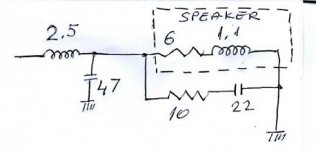
Gosh, it's OK to treat a speaker as 6 ohms in series with 1.1mH in TINA-TI emulator if you are interested in impedance, but frequency response will have little to do with that, being mechanical as well as electrical. 🙂
You'd really need to simulate the whole thing with the speaker files. Someone else can probably advise you on that based on the particular drive units. A 3 way is quite a complicated thing to get right. You'd be very lucky if an off the shelf crossover does very well:
Visaton - Lautsprecher und Zubehör, Loudspeakers and Accessories
Nothing stopping you doing Boxsim with the 1.2mH W170S which is not dissimilar and a couple of other choicely chosen visaton units, but only for fun:
Visaton - Lautsprecher und Zubehör, Loudspeakers and Accessories
This 'classic' formula as you put it would be fine except for a few things, one is of course that the speaker impedance is not resistive. The sqr(2) is indicated for the phase difference between the reactance of a crossover inductor and a pure resistance. It will change when you use a proper impedance (measure or model).
There is a drawback to applying a simple inductor to a woofer in that they each rise with frequency and so tend to share the available drive, rather than one taking over as the frequency rises.
You could either adjust the impedance using compensation (with a resistor and a capacitor to make it behave more like a resistor), or you can move up to a second order filter. These will work better but none of the three options so far will be spot on, unless you either measure or properly model your impedance.
Then, the frequency response may not want to be rolled off at quite that exact frequency...
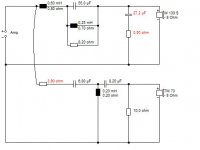
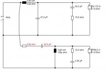
Here is attached drawing of crossover...Will it work as expected? Sugestions appreciated...
Well, knock me down wiv a fevver me ol' china, an' all that, but it's NOT BAD for something you worked out on the back of a beermat! 😀
Very rough little sim with the 1.2mH W170S, but it does OK. I think you undercooked the Zobel a bit. 30uF just tames a 2dB bump at crossover. This is a freestanding speaker due to the big 2.5mH coil which boosts the bass a lot.
I couldn't get phase nearer than 40 degrees at crossover, but I wasn't trying on the midrange end at all. But mate, this approach seems a bit too rough and ready to me. You need better tools. Some drivers just don't get on together at all. You should tell us what they are.
Attachments
Is this your question (if I'm reading it correctly, I will read to the end of the thread), short answer is yes. Higher value inductance gives a more accentuated curve graph.Does taking the voice coil inductance into account give you a rough idea of the impedance curve?
Yes. It's like, "Tell us how to make crossovers in one day" without their correspondent drivers outputs and phases...😀😀😀 or frd's and zma's if you mind me.... You should tell us what they are.

Thanks everyone for inputs, it was helpful. I have attached diagram of my final work, please feel free to coment..
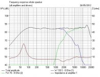
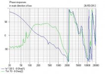
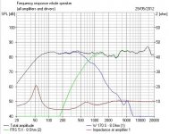
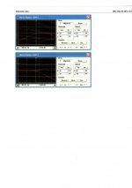
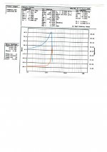
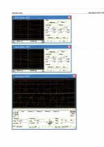
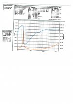
Also, I have attached relevant informations for those who were interested, of Midrange and Woofer... Also, Magnitude plot and Phase plot for crossover. I managed to achieve phase diferece between woofer and mid of 10" or just under, which I think is not bad at all,... Oscilloscpe show that sine waves are almost identical (of course, they have to be reversed in respect to each other, once speakers are in the box). If measurements inside the box confirm it, I will be very satisfied...
Also, I have attached relevant informations for those who were interested, of Midrange and Woofer... Also, Magnitude plot and Phase plot for crossover. I managed to achieve phase diferece between woofer and mid of 10" or just under, which I think is not bad at all,... Oscilloscpe show that sine waves are almost identical (of course, they have to be reversed in respect to each other, once speakers are in the box). If measurements inside the box confirm it, I will be very satisfied...
Attachments
Actualy, it took a bit more effort than back of beermat😉, and longer than one day (inductor)😀... Actualy, several months, from the day I received speakers, did some modifications to woofer (and small one to midrange), did measurements, etc...
I think you're being far too coy here, Tomom. I still can't visualise what you are doing at all. Is it all "Top Secret"? 😀
This forum attracts a lot of people who are actually absolutely top in the field and have built some awesome speakers that are highly respected. I don't include myself in that category, BTW. To engage them, you have to be very straightforward.
3 way speakers are an interesting topic. Troels has published a couple of very nice designs along with good articles:
Poor Man'
3-Way Classic
High Efficiency Speakers
BTW, I think you may be missing a trick on that bass crossover. A little 1 or 2 ohm resistor on the bass capacitor can do nice things to phase, though the Zobel may affect that a bit.
There is no "top secreet"; I noticed that formula from the book is giving me one value for the inductor, but it does not work in simulator and I have to change it, usualy by the value of the VC inductance. So I just wanted to know if this is the way to go, and why formulas do not mention that. I'm working on a three way system, 15" woofer, 6" mid and a tweeter. I am far from top in the field, but I want to do things to perfection as much as I can...
- Status
- Not open for further replies.
- Home
- Loudspeakers
- Multi-Way
- CROSSOVER calculation...