Im working on an amp and want to add a standby switch. It is tube rectified with a 5V4G and the question is to put it before or after the first stage of filtering (an CLC filter) in order to prolong the rectifier life?
(After the CLC filter is the power tube B+ tap, followed by an RC to the preamp)
My thought process is putting it right after the rectifier will be harder on the rectifier when the amps is turned off standby. With the tubes warmed up, the rectifier will draw lot of current due to the uncharged capacitance.
If I put the switch after the CLC filter... If the rectifier is cold and warms up while charging the first CLC caps, it will sort of "trickle charge" them since the cold rectifier cant instantly draw is max current and thus prolong its life.
Is this correct?
Last edited:
Standby switch like used in guitar amps that is tube rectified is after the rectifier and before the filter.
the standby switch was made to kill the B+ to guitar amps wile on break and its was an added feature.
If you have a lot of capacitance, I would suggest going to a Solid state rectifiers ( two 6A10) and use a DPDT switch between the secondary and the solid state rectifiers
the standby switch was made to kill the B+ to guitar amps wile on break and its was an added feature.
If you have a lot of capacitance, I would suggest going to a Solid state rectifiers ( two 6A10) and use a DPDT switch between the secondary and the solid state rectifiers
If you're going to switch B+, pay careful attention to the switch rating.
A better way to do that is the way I saw on an old PA amp I have. To put it in standby, it switches something like -80V onto the grids of the power tubes. This of course assumes you have that kind of voltage available.
A better way to do that is the way I saw on an old PA amp I have. To put it in standby, it switches something like -80V onto the grids of the power tubes. This of course assumes you have that kind of voltage available.
When you think carefully about it, you will probably realise that there is no good place to add a standby switch. Then you will wonder why you want to add a standby switch. Guitar amps have one because musicians expect to see one, and believe it does something useful.
A (real) Standby switch allows a guitarist to leave his amp correctly adjusted for the desired sound,
while switching off any output to the speakers.
This prevents all kinds of mishaps, such as feedback,
noise from knocked-over guitars,
pranks by drunken bar patrons,
unauthorized attempts to play instruments etc.
No single idea will be a solution to everything,
but a standby switch can be practical in many situations.

But from your post you mean a 'warm-up' switch, not a 'standby'.
The difference is quite startling, in both purpose and effect.
The 'warm-up' switch allows the power to be turned on,
and tube-heaters to be warmed up, before applying high-voltage to tubes,
which risks cathode-stripping and early tube failure.
The best way to do this is to automate the process as much as possible.
This begins by a two-part process:
(1) A surge-protector in the heater circuit prevents 'cold-resistance' surges that overflex the heaters and can break them (just like a lightbulb burns out 90% of the time when it is switched on and off). Usually this can be achieved with a Variable resistance Thermistor-type device in series with the heaters. At first the device presents a high resistance, preventing blasts of current to the tube-heaters. As the device warms up it decreases in resistance, allowing full voltage across the heaters once they are warm and present enough resistance themselves. This circuit must only be used when the High Voltage is off or low, so a second circuit is controlled by a relay in the heater circuit. This prevents HV from turning on if the heater-circuit is malfunctioning.
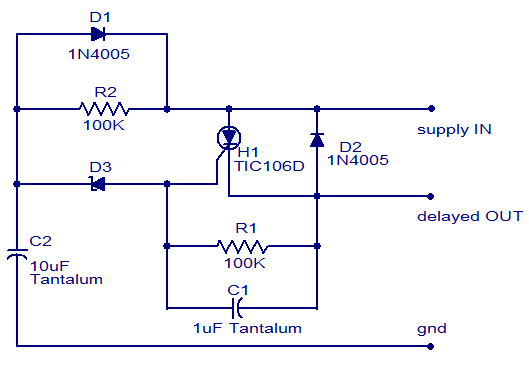
(2) HV Delay. At first, the HV is not shut off completely, which would not solve the problem of capacitor-surge in the HV circuit when first charging. Instead, a large resistor is in series with the High Voltage secondary, preventing a surge as the capacitors first charge. A 30 second delay/relay allows the heater circuit to turn on the full HV by bypassing the resistor, when the heaters have warmed up.
(Example only!!!):
If designed well, the two circuits each contribute to long tube life and power-supply reliability, by allowing 'slow charging' of capacitors, and 'slow warmup' of heaters, before full HV is applied to tubes.
(3) The 'standby' is applied independently and is usually a manual switch that can simply shut off the HV manually at the c.t. / ground point. It is also usually bypassed with a HV cap to prevent or limit arcing inside the switch, just as other components are partially bypassed.
(4) Other components are also protected:
while switching off any output to the speakers.
This prevents all kinds of mishaps, such as feedback,
noise from knocked-over guitars,
pranks by drunken bar patrons,
unauthorized attempts to play instruments etc.
No single idea will be a solution to everything,
but a standby switch can be practical in many situations.
But from your post you mean a 'warm-up' switch, not a 'standby'.
The difference is quite startling, in both purpose and effect.
The 'warm-up' switch allows the power to be turned on,
and tube-heaters to be warmed up, before applying high-voltage to tubes,
which risks cathode-stripping and early tube failure.
The best way to do this is to automate the process as much as possible.
This begins by a two-part process:
(1) A surge-protector in the heater circuit prevents 'cold-resistance' surges that overflex the heaters and can break them (just like a lightbulb burns out 90% of the time when it is switched on and off). Usually this can be achieved with a Variable resistance Thermistor-type device in series with the heaters. At first the device presents a high resistance, preventing blasts of current to the tube-heaters. As the device warms up it decreases in resistance, allowing full voltage across the heaters once they are warm and present enough resistance themselves. This circuit must only be used when the High Voltage is off or low, so a second circuit is controlled by a relay in the heater circuit. This prevents HV from turning on if the heater-circuit is malfunctioning.
An externally hosted image should be here but it was not working when we last tested it.
(2) HV Delay. At first, the HV is not shut off completely, which would not solve the problem of capacitor-surge in the HV circuit when first charging. Instead, a large resistor is in series with the High Voltage secondary, preventing a surge as the capacitors first charge. A 30 second delay/relay allows the heater circuit to turn on the full HV by bypassing the resistor, when the heaters have warmed up.
(Example only!!!):
An externally hosted image should be here but it was not working when we last tested it.
If designed well, the two circuits each contribute to long tube life and power-supply reliability, by allowing 'slow charging' of capacitors, and 'slow warmup' of heaters, before full HV is applied to tubes.
(3) The 'standby' is applied independently and is usually a manual switch that can simply shut off the HV manually at the c.t. / ground point. It is also usually bypassed with a HV cap to prevent or limit arcing inside the switch, just as other components are partially bypassed.
(4) Other components are also protected:
a) For example, the caps will be bypassed by a resistor that discharges them a few seconds after shutdown, and
b) the PS diodes are usually bypassed by large resistors to prevent exceeding their reverse-breakdown voltages with spikes.
c) the Mains transformer is protected by HV bypass caps, and
d) the Output transformer is protected by a high-value resistor across the secondary to prevent voltage spikes from breaking the insulation down inside the xformer.
Attachments
Last edited:
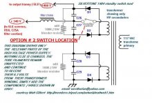
An externally hosted image should be here but it was not working when we last tested it.
In this diagram,
an 8 ohm 5 watt resistor is in series with the HV secondary.
This is primarily a voltage-adjusting resistor,
but it has a side-benefit in that it limits current too,
which protects the power supply capacitors from surges on startup.
The idea with a 30-second delay relay is to switch
a resistor like this (but much larger,) out of circuit,
after the heaters have warmed up, and the caps are safely charged.
Υes, you have to specify whether you d like a slow-start switch that you re going to use only when you apply power from cold, or a standby switch that you ll use to mute the amp. Both can be implemented easily.
Im working on an amp and want to add a standby switch./QUOTE]
Here is a web page just on this subject.
The Valve Wizard
- Status
- Not open for further replies.
- Home
- Amplifiers
- Tubes / Valves
- Add Standby Directly after Rectifier, or After First Filter Stage?