I don't see any feedback from the output. I see a unity gain op amp driving an emitter follower with a constant current load.
Did you also look at/sim the bias currents through Q2 and Q3?
jan didden
I'm sorry, are you addressing me or RJM?
Sorry, RJM. I am afraid that Q2 and Q3 currents vary all over the place and will be too high practically.
Hence the Q.
jan
Hence the Q.
jan
Jan, is this what you wanted?
It's not a complete circuit, I'm still playing with it. The one I have will drive capacitive loads and this one will not. I was just wondering what kind of feedback do you call this?
It's not a complete circuit, I'm still playing with it. The one I have will drive capacitive loads and this one will not. I was just wondering what kind of feedback do you call this?
Attachments
Last edited:
Something like that. But I really just want to know what you call the type of feedback where you control the current through the output transistor, Q1.
Jan, is this what you wanted?
It's not a complete circuit, I'm still playing with it. The one I have will drive capacitive loads and this one will not. I was just wondering what kind of feedback do you call this?
Yes thanks, looks better than I thought. I missed the .25A CCS.
I don't see a feedback loop here either.
The CCS sets the current in Q1 and the voltage drop across the .25A CCS adjust itself to accomodate the delta betweenthe 24V and 15V supplies.
There is a local loop around Q2 and Q3; did you mean that?
jan
Last edited:
Huh, yeah I missed that 0.25 A CCS also!
So, you appear have I1 providing CC to both Q1 and Q3, with Q3 providing a CC to the base of Q2. This isn't feedback as far as I can see. I'm not an expert though. The base voltage of Q3 is fixed by the 15V supply. I think there's a far more simple way to do this, assuming you just want a CC load on your emitter follower output device.
So, you appear have I1 providing CC to both Q1 and Q3, with Q3 providing a CC to the base of Q2. This isn't feedback as far as I can see. I'm not an expert though. The base voltage of Q3 is fixed by the 15V supply. I think there's a far more simple way to do this, assuming you just want a CC load on your emitter follower output device.
This circuit is better than just a constant current load. It maintains constant current (neglecting the beta of Q2 and the alpha of Q3) in Q1. In the limit, that makes the Vbe of Q1 independent of load current. That removes all distortion between the output of U1 and Vout. There are a few practical touches it needs, but the overall concept is worthwhile…I’m not sure, but I vaguely recall a scheme of similar effect in the Pass Stasis amps.
Agreed...this circuit doesn't depend upon hfe accuracy, but only that the hfe is high...that can be achieved by many means.
This circuit is better than just a constant current load. It maintains constant current (neglecting the beta of Q2 and the alpha of Q3) in Q1. In the limit, that makes the Vbe of Q1 independent of load current. That removes all distortion between the output of U1 and Vout. There are a few practical touches it needs, but the overall concept is worthwhile…I’m not sure, but I vaguely recall a scheme of similar effect in the Pass Stasis amps.
I don't fully understand the output stage for this circuit but it seems to me that if he had loop feedback the output impedance would be lower and he wouldn't need all of that fancy constant current circuitry. He's not swinging a huge voltage with this circuit so why all the bother? But, to each their own. What ever. 😕
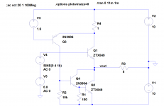
The low distortion is due to the fact that the sense transistor Q3 has high gain. So if the current in the emitter follower Q1 tries to change, the current in Q2 is changed accordingly. The effect is that the current in Q1 is almost constant, reducing distortion. I agree that the current source is really not needed, a resistor can do the job (if the supply voltages are regulated). Notice that the output has a large offset, so it is necessary to have a form of level shift ahead of Q1.
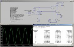
The nice thing about this is that before additional feedback, the output stage has been nicely linearized since the output device Q1 has constant current. Enclosed is a schematic that uses knutn's resistor suggestion...It sims really well. Note that the output impedance is already quite low, as it should be, since Q1's base-emitter voltage is essentially independent of load current.
If we had used the usual constant current source in the emitter of Q1, then Q1's current would swing dramatically, adding distortion to the output stage.
If this stage can be wrapped in a feedback loop, it would probably be really linear. That should be pretty straightforward to do.
If we had used the usual constant current source in the emitter of Q1, then Q1's current would swing dramatically, adding distortion to the output stage.
If this stage can be wrapped in a feedback loop, it would probably be really linear. That should be pretty straightforward to do.
Attachments
The output swing is limited by the product of the load resistance and the constant current. As a quick example, if you wanted to deliver 60 Watts RMS into 8 Ohms, you'd need a peak current of 3.87 Amps. That says you'd be dissipating (with no overhead) about 240 Watts from a power supply, so of course, this thing is kind of class A...but it can be quite linear, it seems...(apologies if I missed a decimal point, but it seems reasonable)
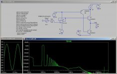
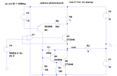
Here I've wrapped a bit of feedback around it, and added some needed stabilization components for the constant current feedback loop. We're not quite real yet...but the simulated performance is quite impressive.
Update My Dynaco
Update My Dynaco
Attachments
- Status
- Not open for further replies.
- Home
- Amplifiers
- Solid State
- What kind of feedback do you call this?