Hi,
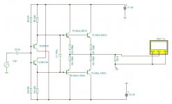
I have build hybrid amplifier - moskido. It is aikido preamp driving mosfet push-pull follower in class A.
I would like to change the output mosfets to bjt. Is the attached schematics ok? Will aikido preamp be able to drive it with 10mA output current?
Thanks.
I have build hybrid amplifier - moskido. It is aikido preamp driving mosfet push-pull follower in class A.
I would like to change the output mosfets to bjt. Is the attached schematics ok? Will aikido preamp be able to drive it with 10mA output current?
Thanks.
Attachments
It would work but the drivers would dissipate around 4-5 watts each.
However at low power, thd would pe pretty good at 0.00x% and near clipping about 0.3%
You may want a DC servo though, as my simulation puts a 1 volt dc offset on the output.
And i dunno if this design would be prone to thermal runaway, try to build it and see.
Bias would be in the ballpark of 500-1000mA per output pair according to LTspice, depending on the value of the emitter resistors combined with the resistors in the driver stage..
Your preamp will also need to be able to give output of atleast 20 volts either direction to be able to get any real power out of it.
I may build it too just because im a bit curious what it'd sound like, its the first non feedback circuit i've simulated that gives me less than 5% THD.
It's actually similar to my latest headphone amplifier.
also u need absolute minimum 10 watt resistors for the 200 ohm resistors in the driver stage.
It's actually similar to my latest headphone amplifier.
also u need absolute minimum 10 watt resistors for the 200 ohm resistors in the driver stage.
Last edited:
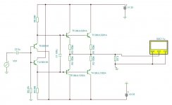
I would increase r4 and r6 to at least 560 ohm, 4 watts is too much to run the drivers at. Even reduced to 1.5 with the 560 ohm resistors they need heatsinks. No need for r8,r9 use a single resistor from the bases of t8,t12 to ground.
If I remove R8 and connect R9 to ground, I cant adjust DC offset by pot. If I change R4 and R6 to 560R the output bias decrease to cca 350mA, which is too low for me. I am aming at 500mA to 600mA.
Attachments
Last edited:
Member
Joined 2009
Paid Member
I may build it too just because im a bit curious what it'd sound like, its the first non feedback circuit i've simulated that gives me less than 5% THD.
did you also look at a JLH follower output - take the JLH 10W classic, pull off the input device, change the splitter/driver from npn to pnp and you are there. Low distortion. It has something in common with your design in that the top half looks like that of a diamond buffer.
- Status
- This old topic is closed. If you want to reopen this topic, contact a moderator using the "Report Post" button.
- Home
- Amplifiers
- Solid State
- Class A BJT buffer for tube preamp