In a other thread i am writing about a 6N16 preamp, in this thread i also started to build a headphone amp. Now i think it is better to give this amp his own thread.
http://www.diyaudio.com/forums/tubes-valves/206415-6n16-12x-preamp-srpp-cathode-follower-printed-circuit-board-design.html
This is what i have done until yet.
Schematic 6N16 headphone amp.

PCB design(100x160mm).

Pdf fot creating PCB film.
http://www.monstercore.nl/6n16hoofdpcb.pdf
I tested the design and got a sample of the sound i can expect.
The PCB board have different possibilities for the output capacitor, this is because there are a lot of people with there own preferences. Below some possibilities for the output capacitor.
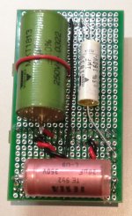
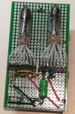
Today i assembled the PCB board with the parts i already got.

Ronny
http://www.diyaudio.com/forums/tubes-valves/206415-6n16-12x-preamp-srpp-cathode-follower-printed-circuit-board-design.html
This is what i have done until yet.
Schematic 6N16 headphone amp.
PCB design(100x160mm).
Pdf fot creating PCB film.
http://www.monstercore.nl/6n16hoofdpcb.pdf
I tested the design and got a sample of the sound i can expect.
The PCB board have different possibilities for the output capacitor, this is because there are a lot of people with there own preferences. Below some possibilities for the output capacitor.
An externally hosted image should be here but it was not working when we last tested it.
Today i assembled the PCB board with the parts i already got.
Ronny
Last edited:
No need for the second 1M resistor in each channel, as U2B get bias from the 10k grid stopper.
The volume pot will eventually become noisy, due to grid current from the valve passing though the wiper. Add a cap and grid leak resistor to avoid this.
The volume pot will eventually become noisy, due to grid current from the valve passing though the wiper. Add a cap and grid leak resistor to avoid this.
Thank you,
for your input.
About the 1M resistor i leave it there i like the stage as parallell as possible.
The grid resistor i will ad and the capacitor is already on the grid on the PCB.
Ronny
for your input.
About the 1M resistor i leave it there i like the stage as parallell as possible.
The grid resistor i will ad and the capacitor is already on the grid on the PCB.
Ronny
The end result plays beatiful without humm and noise.
Deep bass with enough power to play at high levels.
Ronny
An externally hosted image should be here but it was not working when we last tested it.
Deep bass with enough power to play at high levels.
An externally hosted image should be here but it was not working when we last tested it.
An externally hosted image should be here but it was not working when we last tested it.
Ronny
I designed a big brother for the 6n16headphoneamp, the 6n6headphoneamp.
This amp can deliver enough power to drive headphones like AKG K701.
It is a very simple design with great sound. No humm or hiss.
And not to expensive to build, even when you select good low esr capacitors and special PIO capacitors.
Datasheet 6n6p : 6N6P.pdf
This amp can deliver enough power to drive headphones like AKG K701.
It is a very simple design with great sound. No humm or hiss.
And not to expensive to build, even when you select good low esr capacitors and special PIO capacitors.
An externally hosted image should be here but it was not working when we last tested it.
Datasheet 6n6p : 6N6P.pdf
Last edited:
It seems to me that the supply voltage is a little too low.
The performance would be better with 100 V...120 V as +Ub.
Why did you choosed only 75 V ?
The performance would be better with 100 V...120 V as +Ub.
Why did you choosed only 75 V ?
1. Reverse biased electrolytic drawn;
2. No grid leak resistor for 1'st tube,
3. Is it 10 Ohm cathode bias resistor for cahthode follower?
"Who can't design build kits for others"
2. No grid leak resistor for 1'st tube,
3. Is it 10 Ohm cathode bias resistor for cahthode follower?
"Who can't design build kits for others"
It seems to me that the supply voltage is a little too low.
The performance would be better with 100 V...120 V as +Ub.
Why did you choosed only 75 V ?
If the tubes have a bias around 20mA that i like most. First stage draw 19ma en the second stage draw 44ma(2 x 22ma). That with the 75V supply.
Further i have a lot of 2 x 15V transformers so i do not have to buy another one.
The highvoltage transformers are much more expensive here in Netherlands. 24VA transformers with 2 x 30V cost here 8 euro, highvoltage transformers start at 40 euro. Because of the low Ri of the 6n6 you can get high bias with low anode voltage and it sounds good.
Last edited:
1. Reverse biased electrolytic drawn;
2. No grid leak resistor for 1'st tube,
3. Is it 10 Ohm cathode bias resistor for cahthode follower?
"Who can't design build kits for others"
It function as drawn and build. Just try it. And leave then comments.
Sorry, but it looks just weird.
The "SRPP" stage shares 75v between two 6N6P triodes - each one sees 37 volts. No way you can get 19 mA through them... looks like you have them biased at about 4 mA and -0.4volts???!
You should R-C decouple the voltage amplifier from the CF stage: the currents drawn by the CF will modulate the (shared) power supply!
The cathode follower is not the most musical stage. Its output impedance (=Ra/mu) is modulated by the music signal, and Ra is not constant when the current changes.
You could try to CCS load the CF, or just increase the B+ voltage to 150v (as you should have done in the first place) and use a White cathode follower.
The SRPP is the weakest link of the amplifier due to low +Ub.
I made some simulations of the SRPP-stage with different supply voltages.
In all cases the output voltage was 2,7 Vrms. The results were as follows:
+ Ub / THD
75 V...... 0.6 %
100 V..... 0.26 %
120 V .....0.15 %
With 75 V the cathode current of the SRPP stage was 5.1 mA and with 120 V it was 9.7 mA.
Sorry, but it looks just weird.
The "SRPP" stage shares 75v between two 6N6P triodes - each one sees 37 volts. No way you can get 19 mA through them... looks like you have them biased at about 4 mA and -0.4volts???!
You should R-C decouple the voltage amplifier from the CF stage: the currents drawn by the CF will modulate the (shared) power supply!
The cathode follower is not the most musical stage. Its output impedance (=Ra/mu) is modulated by the music signal, and Ra is not constant when the current changes.
You could try to CCS load the CF, or just increase the B+ voltage to 150v (as you should have done in the first place) and use a White cathode follower.
It is weird. About the current you are right, i measure 1.9ma and not 19ma. My fault.
RC decoupling of the two stages i shall try. But first i shall measure if there is a significant voltage drop/ swing.
About the choice of stages there is no discussion. I have tryed it all the last 30 years. I do not like the sound of CSS. Futher i do not want the best specs. i just want music i can listen to for several houres. For me i just need distorsion > 0.5%, no humm, no hiss. And as less parts as possible, so i can pick the parts and evaluate they influence on the sound.
The SRPP is the weakest link of the amplifier due to low +Ub.
I made some simulations of the SRPP-stage with different supply voltages.
In all cases the output voltage was 2,7 Vrms. The results were as follows:
+ Ub / THD
75 V...... 0.6 %
100 V..... 0.26 %
120 V .....0.15 %
With 75 V the cathode current of the SRPP stage was 5.1 mA and with 120 V it was 9.7 mA.
You are right about the distorsion. At 3Vrms i hear the distorsion that is for me a reference that the distorsionlevel is about 0.5%.
My headphone plays at that level(3Vrms) very loud, so i will listen below that level.
I started this schematic at 200V anodevoltage and looked how low i can go. And so i ended up at 75V where i have more then enough power to drive my AKG K701. The 6n16 variation was a little to week to do that.
Last edited:
- Home
- Amplifiers
- Tubes / Valves
- 6N16 headphone amplifier