no no no.
around 0.5V over R10 i guess.
it depends on your heatsinks and transformer.
OK. I think I need to read more (if all the info is in this thread)
Thanks.
I built the JLH amplifier in the middle of 1970's and I remember that it was was a real breakthrough, compared to usual class B and AB designs of those days. It sounded very clean, full and natural.
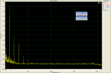
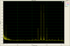
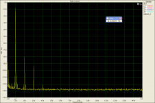
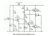
So I have just decided to give it a chance again and to build it with modern solid state devices. I like the original design of 1969 most, for its simplicity and elegance. I have built a sample on a prototype board and supplied it only with +25V supply, which I have unused at the moment. The 1st transistor is BC560, driver is BD139 and output devices are MJL21194. Even with this low supply voltage, the results are stunning. The amplifier is completely free of higher harmonics at any level below clipping, which is the key to its good sound. The OLG is constant high above the audio band. I will probably build a complete stereo amplifier, as I am very curious how it would sound compared to recent amplifiers.
So I have just decided to give it a chance again and to build it with modern solid state devices. I like the original design of 1969 most, for its simplicity and elegance. I have built a sample on a prototype board and supplied it only with +25V supply, which I have unused at the moment. The 1st transistor is BC560, driver is BD139 and output devices are MJL21194. Even with this low supply voltage, the results are stunning. The amplifier is completely free of higher harmonics at any level below clipping, which is the key to its good sound. The OLG is constant high above the audio band. I will probably build a complete stereo amplifier, as I am very curious how it would sound compared to recent amplifiers.
Attachments
PMA,
I first heard this amp in 1970, built by an EE friend. I was astonished how good it sounds, and agree with your summary.
I believe that since it is a completely asymmetrical circuit, this explains the low odd orders and pleasing sound to the ear. It is by no means a low distortion amplifier.
I first heard this amp in 1970, built by an EE friend. I was astonished how good it sounds, and agree with your summary.
I believe that since it is a completely asymmetrical circuit, this explains the low odd orders and pleasing sound to the ear. It is by no means a low distortion amplifier.
I suspect that this lovely amp may lack grip in the bass department. Contributing factors will be o/p stage bias current & o/p cap.
Could be ideal for Mid & treble driving into a passive crossover with something more powerful for bass.
I would suggest 2A minimum bias for bass duties.
Could be ideal for Mid & treble driving into a passive crossover with something more powerful for bass.
I would suggest 2A minimum bias for bass duties.
Hi Mikelm,
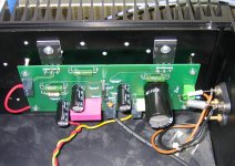
I built it a few month ago using a 27VDC SMPS (single rail) into 40 000uf resevoir and 4700uF output cap with bias set at 1.5A. You will be very surprised at the quantity and quality of the bass, I like jazz and the acoustic bass sounds absolutely realistic.
Granted, you cannot blow the windows out so Pink Floyd may be out of the question, I guess, but listening to the original design at reasonable listening levels is a very enjoyable experience.
Last edited:
HOW TO ADJUST BIAS
Hi all
I build the JLh 69 with the original schematic with a 24 V in . This is powering a 8R speaker.It is very nice .
Can you tell me how to adjust the bias in the circuit? Is it R1 adjustment and measuring the current input ?
Sorry for such a simple question
thanks
kp93300
Hi all
I build the JLh 69 with the original schematic with a 24 V in . This is powering a 8R speaker.It is very nice .
Can you tell me how to adjust the bias in the circuit? Is it R1 adjustment and measuring the current input ?
Sorry for such a simple question
thanks
kp93300
Attachments
Member
Joined 2009
Paid Member
You can adjust either R1 or R2, or both. Increase the values to decrease the current. Reduce the resistor values to increase the current.
To measure the current it will be best if you add a new low value resistor into the circuit, into the collector lead of TR2. Then measure the voltage across the resistor. The current is calculated from voltage / resistor value. A resistor of less than less than 1 ohm is preferred to avoid dissipating too much heat in the resistor.
You want somewhere in the range of 1.5A of idle current - but the real test is whether your heatsinks get too hot - they will get hot but you should be able to put your hand on them for a good 10s before having to remove them.
Sometime when it is built perhaps you might try using zvn3310a as driver and insert a CCS as i/p load resistor - for me it was an improvement - despite the fact some compensation was then necessary.
The i/p CCS only really works well with a mosfet driver.
Would be interested to hear if you also liked the sound of that mod.
The i/p CCS only really works well with a mosfet driver.
Would be interested to hear if you also liked the sound of that mod.
I am almost as surprised as I was 40 years ago 🙂.
The sound is full-bodied, with great bass impact. The bass impact surprises me, for the reason that this is a low-power amplifier. I expect a lot of fun with this 'redesign' 🙂
The sound is full-bodied, with great bass impact. The bass impact surprises me, for the reason that this is a low-power amplifier. I expect a lot of fun with this 'redesign' 🙂
... and there is absolutely no initial thump audible, though it is a single rail PSU version with output capacitor. This is probably due to RC time constant (exponential charging) of the filter before the voltage divider used for DC bias of the 1st transistor.
JLH . . . a genius who understood the value of simplicity!
Definitely.
JLH . . . a genius who understood the value of simplicity!
I agree.
I am trying to adjust the tempco of the input transistor and it's CCS to minimise drift in the output offset.
I have been at it for over 4 hours today and a couple of hours yesterday and I'm not in the ballpark yet. I think I am getting closer.
I have been at it for over 4 hours today and a couple of hours yesterday and I'm not in the ballpark yet. I think I am getting closer.
JLH . . . a genius who understood the value of simplicity!
I agree about the genius but he also understood the value of complexity is his highly respected later designs 🙂
- Home
- Amplifiers
- Solid State
- JLH 10 Watt class A amplifier