I have been working on building a precision test jig to be able to match mosfets and to try and understand the matching process better. I have read the articles by Pass and Elliot and there is still something I am missing. I understand the basic process but there is much to the subject that I have questions about.
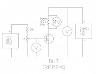
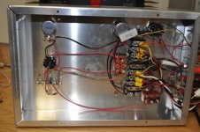
The new rig uses two regulated power supplies. a 0-100V precision adjustable supply that is stable without adjustment to .1v or less. and a 15V regulated bias supply.
I found some very nice and expensive Carlo Gavazzi industrial digital meters on ebay and some 1 ohm .25% 10 watt 4 lead precision resistors.
I configured one CG meter as a MV reading meter and placed it across the 1 ohm resistor. so now any voltage across the resistor is a 1:1 Mv/Ma. 25Mv = 25Ma. I configured the other CG meter to read voltage from the 0-100V supply.
I configured a 20 turn 1K pot and a 1.5K resistor and a 15V regulated supply as a bias supply and i used my Fluke 189 to read the voltage from gate to source.
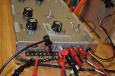
The DUT is clamped to a large heatsink with a T-handle locking clamp. the HV supply is adjusted to whatever voltage you want to match at and then you adjust the bias supply to obtain whatever current you want through the device.
I just tested a batch of 25 IRFP240 and 20 IRFP9240 devices and found some interesting results which i will upload from the spreadsheet later. But what was interesting to note was that the Vgs changes slightly from device to device. without a device plugged in the voltage would drop a little bit. when a device was plugged in, this voltage would rise slightly. I was able to maintain the bias within .001v but some devices would cause a fluctuation of as much as +/- .010v but most were less than .003v. I would tweak this to stay within .001v
I first tested at 15V, then at 70V both at 53Ma as that is the bias current through each device in the amp they are going into.
The N-channel devices ranged from 53ma my starting point up to 90ma and i was able to find 5 that were within 5ma of each other. taking into account temp rise of the heatsink and any other introduce-able errors into the setup. that seemed to be about as close as i could get.
The P-channel devices had a MUCH wider range!!! starting at 53ma I saw as high as 170ma!! it was much more difficult to select 5 devices from this lot! But also of note is that not once did the bias supply need tweaking to maintain exact voltage within .001v! not once!
Some devices were very close in ma from 15V to 70V others had a wide spread. the P-channel devices had a much much wider spread then the N- channels.
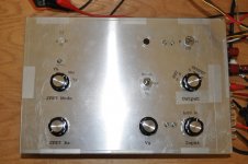
So far the rig seems to work well. I need to do some more work to add an automated timer or some other function to be able to more closely take repeatable readings from device to device. I think that's where my greatest error is at the moment is not being able to take readings at the exact same amount of time after power is applied from device to device. The heatsink is large enough to maintain a close temp but some temp rise was noted. this i think is the 2nd largest error in the test process. and maybe i need to add a timer function to allow the heatsink to settle between testing devices. once i get everything stable i need to work on the physical implementation of the rig. right now it is built up from several boxes and various parts.
The new rig uses two regulated power supplies. a 0-100V precision adjustable supply that is stable without adjustment to .1v or less. and a 15V regulated bias supply.
I found some very nice and expensive Carlo Gavazzi industrial digital meters on ebay and some 1 ohm .25% 10 watt 4 lead precision resistors.
I configured one CG meter as a MV reading meter and placed it across the 1 ohm resistor. so now any voltage across the resistor is a 1:1 Mv/Ma. 25Mv = 25Ma. I configured the other CG meter to read voltage from the 0-100V supply.
I configured a 20 turn 1K pot and a 1.5K resistor and a 15V regulated supply as a bias supply and i used my Fluke 189 to read the voltage from gate to source.
The DUT is clamped to a large heatsink with a T-handle locking clamp. the HV supply is adjusted to whatever voltage you want to match at and then you adjust the bias supply to obtain whatever current you want through the device.
I just tested a batch of 25 IRFP240 and 20 IRFP9240 devices and found some interesting results which i will upload from the spreadsheet later. But what was interesting to note was that the Vgs changes slightly from device to device. without a device plugged in the voltage would drop a little bit. when a device was plugged in, this voltage would rise slightly. I was able to maintain the bias within .001v but some devices would cause a fluctuation of as much as +/- .010v but most were less than .003v. I would tweak this to stay within .001v
I first tested at 15V, then at 70V both at 53Ma as that is the bias current through each device in the amp they are going into.
The N-channel devices ranged from 53ma my starting point up to 90ma and i was able to find 5 that were within 5ma of each other. taking into account temp rise of the heatsink and any other introduce-able errors into the setup. that seemed to be about as close as i could get.
The P-channel devices had a MUCH wider range!!! starting at 53ma I saw as high as 170ma!! it was much more difficult to select 5 devices from this lot! But also of note is that not once did the bias supply need tweaking to maintain exact voltage within .001v! not once!
Some devices were very close in ma from 15V to 70V others had a wide spread. the P-channel devices had a much much wider spread then the N- channels.
So far the rig seems to work well. I need to do some more work to add an automated timer or some other function to be able to more closely take repeatable readings from device to device. I think that's where my greatest error is at the moment is not being able to take readings at the exact same amount of time after power is applied from device to device. The heatsink is large enough to maintain a close temp but some temp rise was noted. this i think is the 2nd largest error in the test process. and maybe i need to add a timer function to allow the heatsink to settle between testing devices. once i get everything stable i need to work on the physical implementation of the rig. right now it is built up from several boxes and various parts.
Attachments
Last edited:
The main things i need to understand is how to match for reliability for high powered PA amplifier applications. where these amps take a beating night after night often with the clip lights blazing away!
I suspect that authors have suggested matching at bias current for lowest distortion at first watt. Honestly i have no idea why it is suggested as such but that's my guess.
but what about for reliability? wouldn't it make more sense to match under the worst conditions the amp will see...or more specifically the output devices will see? If and that's a big if, my thinking is correct. the case of worst device dissipation will come at 1/3rd power. this would be the point where half the power is being dissipated by the load and half as heat in the output devices.
If current sharing isnt very close under this condition. some devices will do more of the work and get the hottest and if this is repeated night after night. would be the first to burn out. So my thinking would be to the devices so they share as equally as possibly under these conditions.
I also want to understand how to match devices for use as rail switches for Class H amplifiers. The term "switch" is really a misnomer as in most rail switcher amps the devices on the upper rails don't just turn on or off. but act more as predictive voltage regulators to vary the voltage the main output devices see in order to always keep the rails higher then the peak output. So the matching conditions for these devices might be different?
and what about paralleled devices as pass elements for high powered voltage regulators? what parameters would you choose to match at then?
I have been working on building a precision test jig to be able to match mosfets and to try and understand the matching process better. I have read the articles by Pass and Elliot and there is still something I am missing. I understand the basic process but there is much to the subject that I have questions about.
The new rig uses two regulated power supplies. a 0-100V precision adjustable supply that is stable without adjustment to .1v or less. and a 15V regulated bias supply.
I found some very nice and expensive Carlo Gavazzi industrial digital meters on ebay and some 1 ohm .25% 10 watt 4 lead precision resistors.
I configured one CG meter as a MV reading meter and placed it across the 1 ohm resistor. so now any voltage across the resistor is a 1:1 Mv/Ma. 25Mv = 25Ma. I configured the other CG meter to read voltage from the 0-100V supply.
I configured a 20 turn 1K pot and a 1.5K resistor and a 15V regulated supply as a bias supply and i used my Fluke 189 to read the voltage from gate to source.
The DUT is clamped to a large heatsink with a T-handle locking clamp. the HV supply is adjusted to whatever voltage you want to match at and then you adjust the bias supply to obtain whatever current you want through the device.
I just tested a batch of 25 IRFP240 and 20 IRFP9240 devices and found some interesting results which i will upload from the spreadsheet later. But what was interesting to note was that the Vgs changes slightly from device to device. without a device plugged in the voltage would drop a little bit. when a device was plugged in, this voltage would rise slightly. I was able to maintain the bias within .001v but some devices would cause a fluctuation of as much as +/- .010v but most were less than .003v. I would tweak this to stay within .001v
I first tested at 15V, then at 70V both at 53Ma as that is the bias current through each device in the amp they are going into.
The N-channel devices ranged from 53ma my starting point up to 90ma and i was able to find 5 that were within 5ma of each other. taking into account temp rise of the heatsink and any other introduce-able errors into the setup. that seemed to be about as close as i could get.
The P-channel devices had a MUCH wider range!!! starting at 53ma I saw as high as 170ma!! it was much more difficult to select 5 devices from this lot! But also of note is that not once did the bias supply need tweaking to maintain exact voltage within .001v! not once!
Some devices were very close in ma from 15V to 70V others had a wide spread. the P-channel devices had a much much wider spread then the N- channels.
So far the rig seems to work well. I need to do some more work to add an automated timer or some other function to be able to more closely take repeatable readings from device to device. I think that's where my greatest error is at the moment is not being able to take readings at the exact same amount of time after power is applied from device to device. The heatsink is large enough to maintain a close temp but some temp rise was noted. this i think is the 2nd largest error in the test process. and maybe i need to add a timer function to allow the heatsink to settle between testing devices. once i get everything stable i need to work on the physical implementation of the rig. right now it is built up from several boxes and various parts.
Do you have any pictures of your heatsink/clamp setup? I have built a similar test device but haven't found a simple and reliable way to quickly clamp the MOSFETs to the heatsink.
I can see a slight problem with big heat sink
How long does it take to warm up and at which temperature you mesure the mosfets?
I am shure you noticed VGS change as mosfets warm up
Why not use small heat sink and fan
Take VGS at constant themperature forghet time.
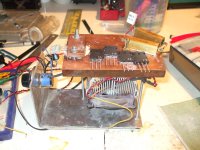
Clamp: 2 nice bolts and big piece of bar on top after a while one get use to tighten up at fairly constan torque.
The small CPU get rid of 50W heat at quite low speed.
As speed is controlled it only takes a minute or so from 47C to get up to 50C
I am testing the mosfets at 24 V 2 amps for F5
Repeating day after day and at much different ambient themperature is newer an issiue I actualy got a couple of mosfets I keep Just for initial start up set system up for those and the rest have to be right..
How long does it take to warm up and at which temperature you mesure the mosfets?
I am shure you noticed VGS change as mosfets warm up
Why not use small heat sink and fan
Take VGS at constant themperature forghet time.
Clamp: 2 nice bolts and big piece of bar on top after a while one get use to tighten up at fairly constan torque.
The small CPU get rid of 50W heat at quite low speed.
As speed is controlled it only takes a minute or so from 47C to get up to 50C
I am testing the mosfets at 24 V 2 amps for F5
Repeating day after day and at much different ambient themperature is newer an issiue I actualy got a couple of mosfets I keep Just for initial start up set system up for those and the rest have to be right..
Attachments
Last edited:
I can see a slight problem with big heat sink
How long does it take to warm up and at which temperature you mesure the mosfets?
I am shure you noticed VGS change as mosfets warm up
Why not use small heat sink and fan
Take VGS at constant themperature forghet time.
Clamp: 2 nice bolts and big piece of bar on top after a while one get use to tighten up at fairly constan torque.
The small CPU get rid of 50W heat at quite low speed.
As speed is controlled it only takes a minute or so from 47C to get up to 50C
I am testing the mosfets at 24 V 2 amps for F5
Repeating day after day and at much different ambient themperature is newer an issiue I actualy got a couple of mosfets I keep Just for initial start up set system up for those and the rest have to be right..
Thanks for the picture. Looks good.
Are you saying that there is a small CPU chip on the heatsink side of the copper block to heat the block up? What are the large resistors for the MOSFET load? Do you have a schematic for the temperature control?
The CPU fan thing is there to keep plate at 50 C constant themperature
Heat is provided by the mosfet on test as I am running 24 V 2A bias or about 50 W
The resistors are there as sources resistors as in Papa article matching mosfets for audio actualy I am using a Futaba 0.47 latley (same for the F5) as if I make condition the same as in the amplifier I use it would be better.
The circuit for the temperature controll is a simple voltagge divider made up with a couple of thermistors (same as F5) and a multyturn pot controlling the gate voltagge on a mosfet.
as temperature go up thermistor resistance go down Volts at gate go up fan turn faster and thing cool down.
After a while is quite easy to adjust the multy turn to achieve equilibrium at your temperature of choice.
Here are the files you may need
If you are serious about testing you may also consider this
http://www.diyaudio.com/forums/solid-state/151253-diy-curve-tracer-pc.html
I got one and it really realy works
I have cross tested both methods and whicever way I got realy good results
matching prety well at 0.001 V
Obwiously if you are matching at low current you are going to need a litle heater to keep the plate at 50 C (I have found that at this setting changes in ambient temperature dont have much efect)
Now litle heater is not a problem Just use another mosfet to keep things warm
Attachments
Bksabath:
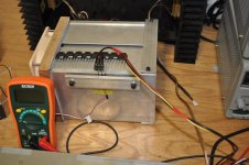
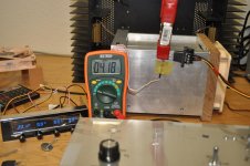
I have built a MOSFET/JFET tester and am attempting to use it to match 25 each of FQA28N15 and FQA36P15 MOSFETs. I am testing at 1.25A, 32V with a 8 ohm load. That gives 27.5 Watts dissipation in the MOSFET. The heatsink temperature stabilizes at very close to 50 degrees C with this dissipation.
I am having some problems getting repeatable measurements. Here is what I have discovered:
1. I get better thermal interface to the heatsink if I smooth the MOSFET contact surface with 600 grit emory paper. I clamp the MOSFETs directly to the heatsink without an insulator. I am trying to avoid using thermal paste so that I do not have to clean the MOSFETs after testing.
2. My transistor test fixture does not make good contact to the MOSFET leads. I find that a 3 pin MOLEX terminal block works much better. Using the test fixture I get variations of 5% or more in measurements of transconductance and Vgs. Measurements using the MOLEX terminal block appear to be very repeatable.
Attachments
Hi it is wery similar to my set up altrought I have fliing vires (your look much tidier) and I use CPU cooler
That sems to reduce time lags as sink look smaller and warm up faster
then circuit in dravings adjust fan speed as needed.
I have one meter mesuring the current whic I adjust to 2 amps when the is at 50 C by altering the voltagge to the gate and a second meter to mesure the VGS.
I have posted same results on the curve tracer tread of 2 pairs I have mesured first with the Rig and then with the Curve tracer
results are prety good with both
but curve tracer make thing much easier and faster
Last edited:
BKSabbath,
it appears in the link you added concerning tbe fan controller, you have two methods of controlling fan, one fet based and one regulator based. Is this true? Do you have specifics for your final layout?
it appears in the link you added concerning tbe fan controller, you have two methods of controlling fan, one fet based and one regulator based. Is this true? Do you have specifics for your final layout?
BKSabbath,
it appears in the link you added concerning tbe fan controller, you have two methods of controlling fan, one fet based and one regulator based. Is this true? Do you have specifics for your final layout?
No is only one.
first part is standard LM317 to make 12 V
Final lay out is wery much as shown litle mods on resistor values depending on your sink and fan
For example I have found that 3 thermistors in series (all fitted in same place)make response faster (steeper V out curve)
Or litle 200 Homs multiturn in series with other pot helps a lot in making adjustments.
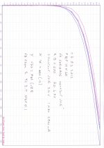
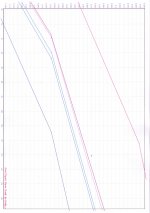
Here a couple of atachments of pairs measured with test rig at first and then with curve tracer
Top curves are 2 devices used as reference the rest can be seen better in picture 2.
I know we are hi jaking this tread so one last OT comment from me
Matching the mosfets that good and source resistors as in F5 can be reduced quite a bit...
Top curves are 2 devices used as reference the rest can be seen better in picture 2.
I know we are hi jaking this tread so one last OT comment from me
Matching the mosfets that good and source resistors as in F5 can be reduced quite a bit...
Attachments
- Status
- Not open for further replies.
- Home
- Design & Build
- Parts
- Mosfet Matching - My new rig