expensive and damn hot. shorter lifetime on your caps.
the regulators themself has to dissepate around 70W.
that meens a lot higher ambient temp in your chassis.
the regulators themself has to dissepate around 70W.
that meens a lot higher ambient temp in your chassis.
It will sound expensive.
😱.....................................

what will happen if :
1. using a 10000uf/71v to handle 24v rails.
2. using dual 0-36v toroidal trafo regulated into 24v.
does it affect the sound quality?
I will get to what happens in a minute as you ask
First question is do you already have those?
Why regulate trafo back to 24?
What Volts x Amps trafo rating? more than 800?
Because if you do already have them you could send them to me for proper disposal free of charge.
Then what happen will be me building super duper 50 V rails F5 with tanks
50 v rails(35 x1.47) mean biasing mosfets at max 1 amp so maybe 6 N&P pairs and cascoded duble imputs.
with 300 W dissipation (50 X6) I will have to use a fan on my sinks (2 X 80 mm units at about 30 % speed ) but that is a sacrifice I am prepared to make.
Actualy I am saving up for just similar components.
Sound quality will be greatly improved when I am having big party as 1812 vill stop clipping and spoil neigbours enjoiment (speaker protection cut off and put F5 in stand-by for 30 seconds or so)
Last edited:
expensive and damn hot. shorter lifetime on your caps.
the regulators themself has to dissepate around 70W.
that meens a lot higher ambient temp in your chassis.
EDIT: 120W not 70W.
If the heath in the box is a problem dont build the box.
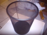
Just stick 4 legs or 3 on the sink and wrap the non fins sides in perforated mesh
cheap to get and easy to cut with decent scisors.
Just stick 4 legs or 3 on the sink and wrap the non fins sides in perforated mesh
cheap to get and easy to cut with decent scisors.
warm room and class A amplifiers are blessing in Uk
Is normaly raining in here as we have 2 kinds of wheater
coldish rain and warmish rain.
This is what I use
Buy Perforated Sheets Perforated steel sheet,1.7mm dia RS 817-426-0002 online from RS for next day delivery.
Yeah do not let the mosfet sit there at bias VGS just play lauder.
Is normaly raining in here as we have 2 kinds of wheater
coldish rain and warmish rain.
This is what I use
Buy Perforated Sheets Perforated steel sheet,1.7mm dia RS 817-426-0002 online from RS for next day delivery.
Yeah do not let the mosfet sit there at bias VGS just play lauder.
The resistors are around .47 ohms (.9 ohms with DMM). More questions to help me with troubleshooting
Are the resistors marked/banded as .47 ohm resistors?
Does your DMM measure them as 0.9 ohms "out of circuit"?
Keep in mind, you may have twice the resistance (0.9 ohms v. .47 ohms) and therefore only half the current flow at the .48 v bias level.
I'd doublecheck those two resistors.
warm room and class A amplifiers are blessing in Uk
Is normaly raining in here as we have 2 kinds of wheater
coldish rain and warmish rain.
This is what I use
Buy Perforated Sheets Perforated steel sheet,1.7mm dia RS 817-426-0002 online from RS for next day delivery.
Yeah do not let the mosfet sit there at bias VGS just play lauder.
yes. but i rather turn up the bias then let some regulators heat my room 🙂
nice ones 🙂
i use this for vents.
Attachments

To small transformer....?
I have a 500va/18vac toroid transformer from Antek that is supplying three F5 channels and I suspect that the transformer is too small. The transformer makes a lot of humming when its turned on.
Iam thinking of getting new ones, but are not sure what would the minimum VA for my configuration. I was thinking of a Antek AN-8420- a 800VA.
Any comments or other suggestion?
you prolly got dc on your net.
 this will cause the torroid to make noise.
less hum with 3-rd channel disconnected from PSU?
be sure that you don't have DC on mains line
be sure that you don't have DC on mains line
500VA 18+18Vac transformer has a maximum continuous AC current rating of 13.9AacI have a 500va/18vac toroid transformer from Antek that is supplying three F5 channels
When feeding a capacitor input filter the maximum continuous DC current rating becomes ~7Adc
Three channels of F5 draw 3.9Adc (3*1.3A of bias) that is ~56% of maximum rating.
I would expect the transformer to be OK for temperature.
It seems likely the transformer is showing symptoms of saturation due to the DC effect of distorted supply waveform.
Caddock MP915 R5/R6 heatsink requirement
Apologies for my ignorance, but I have a question about R11 and R12.
I am building an F5 using standard diy-audio store boards, 24V rails, tech-diy parts kit plus optional Caddock MP915 and MP930 resistor kit (also tech-diy).
I understand that R1 and R2 (Caddock MP915 10R) will not require heatsinks.
I also understand that R5 and R6 (Caddock MP930 50R) will dissipate up to 5.5W (post 11134) and hence require sufficient heatsinking. I asked about placing on the main heatsink and extending the leads and Nelson replied that is OK (post 11128).
I considered placing R11 and R12 on the main heatsink as well, but am wondering if a small heatsink would also be an option. I am not sure how much these resitors will dissipate. I know that the schematic shows a 0.6V drop, so they would see a current of (I = V/R = 0.6 / 0.5 =) 1.2A (surprise, surprise, the bias current). What I do not know (shows the level of understanding, I am afraid) if this current is a constant value or depends on the load. Intuitively I would assume it to be constant, but would hate to blow up the amp on this assumption. 🙂
Assuming the current of 1.2A is correct and constant, R11 would dissipate (P = VI = 0.6 x 1.2 =) 0.7W. I am unsure of the thermal characteristics of the small heatsinks I have (they were no-name brand so no data sheet) but I would expect them to be about 20-30C/W. This should then be sufficient.
Could someone confirm this for me please?
Thanks,
Albert
Some folk will listen to average levels from their speakers ~10% (-10dB) of maximum output.
Others will be happy with average levels of ~0.1% (-30dB) of maximum output.
Taking -20dB as an example that will suit many Members, then the average output power is 1/4Watt.
That equates to an average output current of 180mAac.
Don't worry about the heating effect in the feedback resistors.
It's the change in resistance due to Tj when transient currents flow that may be a concern.
Similarly the Source Resistors see the bias current as the continuous average loading. The transient heating effect can be ignored.
Last edited:
Don't worry about the heating effect in the feedback resistors. It's the change in resistance due to Tj when transient currents flow that may be a concern.
Similarly the Source Resistors see the bias current as the continuous average loading. The transient heating effect can be ignored.
Thanks Andrew, but I am afraid your answer is aimed at a level of understanding I do not have.
I looked up the Caddock datasheet. There is no Tj mentioned. Am I correct to assume that it is the (resistive) film temperature?
yes.Am I correct to assume that it is the (resistive) film temperature?
- Home
- Amplifiers
- Pass Labs
- F5 power amplifier