No, the originals were not specially selected, according to other people here. Nothing is matched or selected.
I would completely disagree - I've seen it numerous times over many years.
If the amp hasn't got adjustable bias, it's because the parts are specially selected - Fender won't select them, they will order them to meet specific more exact requirements, and pay a little more for doing so.
This saves them the cost of a pot, the cost of it needing setting up in production, and means you have to buy their specific spare parts (at MUCH greater expense) rather than buying generic parts.
I've never seen one of these amps, but from the PCB layout it looks easy enough to get to the resistor to solder one across it - assuming you can see one side of the board or the other. But generally when working on these types of amps you take the board out and work on it all the time like that, only reassembling it after it's repaired.
Certainly guitar/PA amps tend to be a pain to disassemble, often because of the huge numbers of knobs and control fixings you have to remove - mixers are even worse!.
No, I don't think that they are matched because in the other amp, the voltages across all of the emitter resistors in the finals are different. If they were matched, wouldn't they all be the same?
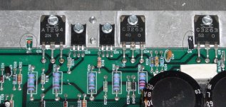
Here is a closeup of the bad amp. I've circled Q16 and a thermister also, which may be involved with the problem, I don't know. The thermister is part RT1 of a power supply regulator. I don't know what it does.
Attachments
No, I don't think that they are matched because in the other amp, the voltages across all of the emitter resistors in the finals are different. If they were matched, wouldn't they all be the same?
I didn't say 'matched', I said 'selected' 😀
If you change the output transistors or drivers in an amp, you have to adjust the bias - if you don't on this Fender, then it's because they fit selected devices.
Here is a closeup of the bad amp. I've circled Q16 and a thermister also, which may be involved with the problem, I don't know. The thermister is part RT1 of a power supply regulator. I don't know what it does.
The thermistor appears to be a thermal safety device, and will shut the amp down if it gets too hot.
Nice picture, with R250 clearly visible to the left of Q16 - nice and easy to solder across! 😀
I didn't say 'matched', I said 'selected' 😀
If you change the output transistors or drivers in an amp, you have to adjust the bias - if you don't on this Fender, then it's because they fit selected devices.
The thermistor appears to be a thermal safety device, and will shut the amp down if it gets too hot.
Nice picture, with R250 clearly visible to the left of Q16 - nice and easy to solder across! 😀
Well, I don't know who did the repair, but it could have been done by Fender, I don't know. I don't know what criteria they would have used to select the drivers and outputs either. I already paid $3 each for Q16. I'm not paying for the outputs also. I'll substitute something cheap and available instead and just make it work if I have to.
It seems extremely crude to just turn off the -16V preamp supply if the amp gets too hot. Maybe that's what the owner means by "it sounds bad after a while".
I think I'll just replace Q16 first to see if it makes a difference. It's unlikely I can get it out without damaging it because there's almost no clearance to grip it with a needle nose pliers.
Well, I don't know who did the repair, but it could have been done by Fender, I don't know. I don't know what criteria they would have used to select the drivers and outputs either. I already paid $3 each for Q16. I'm not paying for the outputs also. I'll substitute something cheap and available instead and just make it work if I have to.
It seems extremely crude to just turn off the -16V preamp supply if the amp gets too hot. Maybe that's what the owner means by "it sounds bad after a while".
Crude but effective 😀
I think I'll just replace Q16 first to see if it makes a difference. It's unlikely I can get it out without damaging it because there's almost no clearance to grip it with a needle nose pliers.
I'm not suggesting you should change the outputs, or even that you should have blown $3 on Q16 - you should have soldered a couple of cents worth of resistor across the top of R250 and see how that reduced the bias. If it DID reduce the bias (and I'm pretty sure it will) then it's pretty certain that there's nothing wrong with Q16. It also means you can do it without removing the PCB.
I'm not suggesting you should change the outputs, or even that you should have blown $3 on Q16 - you should have soldered a couple of cents worth of resistor across the top of R250 and see how that reduced the bias. If it DID reduce the bias (and I'm pretty sure it will) then it's pretty certain that there's nothing wrong with Q16. It also means you can do it without removing the PCB.
I know you are not suggesting that Q16 is bad. Enzo, who apparently has run a Fender repair shop for 25 years, says that it's most likely a bad Q16. I'm getting conflicting suggestions, so I have to pick and choose.
If replacing Q16 does not fix it, then I will investigate changing the resistors around it. I got the 1k trimmer yesterday, as well as some other parts. I'm waiting on Q16.
Hi,
Seven pages in and you still don't know whats going on ....
I'll state that :
You haven't used the working channel to your advantage.
Why put a trimmer in one channel if the other works just fine ?
I would have ascertained that the Vbe multiplier voltages must be different.
I would have swapped Q16's to see the effect. I would have checked both
Q16's are similarly thermally coupled to the heatsink. Something is most
likely amiss in the effective ratio of the Vbe mutliplier resistors, I would
have checked those and their soldering. I would of checked both Vbe
multipliers see the same standing current. I would of found what the
problem is quite quickly because if you understand that part of
circuit its not possible not to identify the problem.
rgds, sreten.
Hi,
Seven pages in and you still don't know whats going on ....
I'll state that :
You haven't used the working channel to your advantage.
Why put a trimmer in one channel if the other works just fine ?
I would have ascertained that the Vbe multiplier voltages must be different.
I would have swapped Q16's to see the effect. I would have checked both
Q16's are similarly thermally coupled to the heatsink. Something is most
likely amiss in the effective ratio of the Vbe mutliplier resistors, I would
have checked those and their soldering. I would of checked both Vbe
multipliers see the same standing current. I would of found what the
problem is quite quickly because if you understand that part of
circuit its not possible not to identify the problem.
rgds, sreten.
thanks for your input. I have very little time to work on this amp, for one thing. I was planning on comparing the two amps the next time I get around to working on it. I have not forgotten your suggestions a while back. Other people say other things, so I have to sift out the conflicting advice and come to my own conclusion. I have compared voltages across the emitter resistors in the finals, as I have stated previously, but have not checked any further yet.
Neither Q16's are thermally coupled to the heat sink. They are proximate, so that's about as good as it gets.
I had a chance to make a quick check of the voltage across Q16 and Q15 (the other Vbe transistor). Both were within a few mV of each other, and falling. From turn on, they were about 2.58~2.60V, but fell to about 2.48~2.50V. I didn't leave it on long enough for them to stop changing.
So, what's up with that?
So, what's up with that?
Nothings wrong with that .
Looks like its just as Nigel says , different tolerance replacement output trannies .
So my vote is for adjusting the bias which ever way is easiest for you .
If you have to take the board out suggest you put in the 1K pot as previously suggested , which you will only need to do once . If you put the pot in dont forget to strap the middle pin to one of the outers .
Nothings wrong with that .
Looks like its just as Nigel says , different tolerance replacement output trannies .
So my vote is for adjusting the bias which ever way is easiest for you .
If you have to take the board out suggest you put in the 1K pot as previously suggested , which you will only need to do once . If you put the pot in dont forget to strap the middle pin to one of the outers .
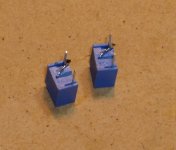
OK! That's great. I think that's right. I got the trimmers. If I finish early with work today I may be able to tear into it. Wish me luck!
PS
Wind the pot up to its max resistance before you put it in or at least before you power up .
Oh yeah! I was actually going to set it to the original resistor value, which I think is about 845 ohms. The sim says that the adjustment is very touchy.
So, I adjust it so that the outputs are nearly turned off and stable? Each of the emitter resistors is 0.15 ohms, so 5mV would be about 33mA each, is that a good number, or something less than that? For what it's worth, the sim says those outputs should be turned off, as in microamps going through each one.
So, what's up with that?
Hi,
Whats up with it is you seem to have the very tedious problem
of different laws of physics and loop mathematics applying to
each channel, which of course they cannot.
Transistor variability is irrelevant to bias schemes, its simply not
the case two properly working channels would be so different.
If the two Vbe multiplier voltages are very similar there is no
point buying and changing the transistors, or fitting a trim pot
to one channel, the problem is elsewhere, if there is one.
If I'm sounding somewhat frustrated that is because I am.
I used to fix stuff, and the only thing that could flummox me
in output stages was hf oscillations causing problems, usually
due to fitted higher Ft replacement devices than original.
Proper investigation always revealed the problem, I found.
rgds, sreten.
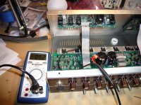
OK! trimmers and other things are installed. The amp is on and sitting there now, and I'll let it sit for a few hours just to be sure it's stable. What I think was happening is that one of the outputs is way off and would start the thermal runaway, dragging the others with it as it got the common heatsink hotter and hotter. The reason I think that is that for these four outputs, there is one that conducts a lot more current for the same bias setting than the others. This one is sitting at 5.2mV, whereas the others in the group are more like 3 or so. The ones in the other amp are more uniform, though there is still one that is out on that side also.
This is a strong argument for matching the outputs!
This is a strong argument for matching the outputs!
Attachments
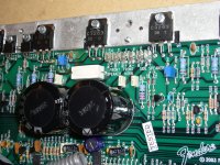
So, it's been siting there for almost 3 hours and that transistor worked it's way up to 5.9mV. I think it's ok now. Everything was just slightly warm. Thank you everyone for your kind help, patience and suggestions. Tomorrow I put it back in the case and put some music through it. Hopefully it will sound good!
OK! trimmers and other things are installed. The amp is on and sitting there now, and I'll let it sit for a few hours just to be sure it's stable. What I think was happening is that one of the outputs is way off and would start the thermal runaway, dragging the others with it as it got the common heatsink hotter and hotter. The reason I think that is that for these four outputs, there is one that conducts a lot more current for the same bias setting than the others. This one is sitting at 5.2mV, whereas the others in the group are more like 3 or so. The ones in the other amp are more uniform, though there is still one that is out on that side also.
That's another reason for the emitter resistors - it balances the paired transistors.
As one of the pair takes more current the voltage across the emitter resistor increases, this means the available voltage at the base is now effectively not as high as it was, so the other transistor starts to take more current instead. This in turn reverses the effect again, the result been that the amp settles down with suitable low currents through both, and equal sharing of the power.
If you didn't have emitter resistors, one of the pair would provide all the current, and the amp soon die.
I know you are not suggesting that Q16 is bad. Enzo, who apparently has run a Fender repair shop for 25 years, says that it's most likely a bad Q16. I'm getting conflicting suggestions, so I have to pick and choose.
My suggestion costs a couple of cents, and PROVES if Q16 is faulty or not - somewhat cheaper than $3 to replace it, to find out it's no different 😀
My suggestion costs a couple of cents, and PROVES if Q16 is faulty or not - somewhat cheaper than $3 to replace it, to find out it's no different 😀
Well, it seems to be working now. I'm going to put it back in the cabinet tonight and put some music through it. Hopefully it will sound OK.
I have spare Q16 and Q15 now... I may need them when some other Fender product slides across my workbench.
Dirk, glad you have it working.
A thought about conflicting advice. Put it all in a context. Clearly I disagree with Nigel on a couple things here. I am not going to storm across the pond and pummel him into agreement with me, I respect his view. I just disagree with it. But looking at any of the advice given, any of these routes will take you closer to your goals. If your table rocks back and forth, someone might advise you put something under the short leg. Others may advise you sand down the long leg. COnflicting advice. We may decide one way is less work, or is simpler, but either approach at least gets the table steady.
I think the bias transistor needs changing, others think the bias transistor is OK and the circuit around it needs changing. Step back and observe that both approaches are saying the bias circuit is the problem.
Nigel thinks the parts are special, and I think they are generic. We can all argue that over a few pints some evening, but a number of people suggested using the other amp in the process. I wanted to swap the bias transistors between the two. A couple minutes and a bit of solder. It would have told us immediately if that transistor was the problem or an innocent victim. Others want to make the circuit adjustable. it isn;t a matter of one way is right and everything else is wrong.
Put on both socks then both shoes? Or put on one sock and shoe, then do the other foot? Conflicting advice, but neither is wrong. But even if one way IS wrong in some fashion, sometimes it is worthwhile to just do something, even if it is wrong.
That leaves bathroom tissue rolls - end over the top or end underneath? Clearly there is a right and wrong there...
- Status
- Not open for further replies.
- Home
- Live Sound
- Instruments and Amps
- Fender Acoustasonic needs help