Hi, folks,
Having fought with that problem for a while, I decided its time to call for help.
Kingneb had similar problem, but with different amplifier and condition.
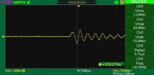
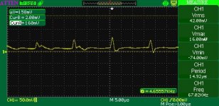
Looks like I have oscillation, around 100 KHz, 12 - 20 mV RMS. At first sight, it may be recognized as a noise, but it is NOT. And here is why.
1) Amplifier power is 60W, thus, RMS output voltage is 22V on 8 Ohm load. S/N ratio = =20*LOG(22/(20/1000)) = 60 dB. Clearly a problem. This kind of amplifier must have S/N ratio around 80 - 90 dB.
2) Distortions (jagged sine-wave) and instability (square wave) on small signal output (100 - 200mV).
3) Instability under certain circumstances (e.g. heavy overload), which leads to oscillation (seen as washed out sine-wave curve).
Amplifier under test loaded with 8 Ohm wire-wound resistor. Power supply is CLC: 200uF + 4H Choke + 200uF. All filament wires are twisted - in case of hum frequency of noise should 50 Hz, not 100 KHz. Input is shorted during measuring noise/oscillation.
On the original schematic there was optional C3/R10 (to suppress oscillation), it is installed.
Then, in order to improve square wave performance, I connected C21/R53, and removed C3/R10. It didn't help to get rid of oscillation. Changing GNFB with R2 trim potentiometer also helpless.
I even turned off LCD monitor and fluorescent lamp on my table, and shielded pre-driver 6N1P.
Original schematic used 6AQ8, 12BH7 and 6L6GC. I replaced these tubes with closest possible substitutes from my collection. Reverting back from 6N1P to 6AQ8 have no effect to oscillation.
Of course, its possible to connect zobel RC network to output terminals, and remove oscillation from oscilloscope, but this is not a real solution for tis problem.
Increasing supply voltage for pre-driver (shorting R31) leads to heavy 200 KHz oscillation, which can be only suppressed with reducing GNFB with trim potentiometer R2 (>= 1K). I have several different output transformers with CFB, 3.9K - 5K, with leakage inductance 8 ... 18 mH, problem the same. Output tubes biased at 60mA, tried Shuguang 6550 and Tung Sol KT120.
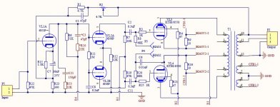
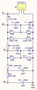
I'm attaching schematic and pictures for reference. Power transformer, rectifiers, HV/B+ CLC filter, BIAS C filter are not shown.
Thanks in advance for any suggestion(s).
Having fought with that problem for a while, I decided its time to call for help.
Kingneb had similar problem, but with different amplifier and condition.
Looks like I have oscillation, around 100 KHz, 12 - 20 mV RMS. At first sight, it may be recognized as a noise, but it is NOT. And here is why.
1) Amplifier power is 60W, thus, RMS output voltage is 22V on 8 Ohm load. S/N ratio = =20*LOG(22/(20/1000)) = 60 dB. Clearly a problem. This kind of amplifier must have S/N ratio around 80 - 90 dB.
2) Distortions (jagged sine-wave) and instability (square wave) on small signal output (100 - 200mV).
3) Instability under certain circumstances (e.g. heavy overload), which leads to oscillation (seen as washed out sine-wave curve).
Amplifier under test loaded with 8 Ohm wire-wound resistor. Power supply is CLC: 200uF + 4H Choke + 200uF. All filament wires are twisted - in case of hum frequency of noise should 50 Hz, not 100 KHz. Input is shorted during measuring noise/oscillation.
On the original schematic there was optional C3/R10 (to suppress oscillation), it is installed.
Then, in order to improve square wave performance, I connected C21/R53, and removed C3/R10. It didn't help to get rid of oscillation. Changing GNFB with R2 trim potentiometer also helpless.
I even turned off LCD monitor and fluorescent lamp on my table, and shielded pre-driver 6N1P.
Original schematic used 6AQ8, 12BH7 and 6L6GC. I replaced these tubes with closest possible substitutes from my collection. Reverting back from 6N1P to 6AQ8 have no effect to oscillation.
Of course, its possible to connect zobel RC network to output terminals, and remove oscillation from oscilloscope, but this is not a real solution for tis problem.
Increasing supply voltage for pre-driver (shorting R31) leads to heavy 200 KHz oscillation, which can be only suppressed with reducing GNFB with trim potentiometer R2 (>= 1K). I have several different output transformers with CFB, 3.9K - 5K, with leakage inductance 8 ... 18 mH, problem the same. Output tubes biased at 60mA, tried Shuguang 6550 and Tung Sol KT120.
I'm attaching schematic and pictures for reference. Power transformer, rectifiers, HV/B+ CLC filter, BIAS C filter are not shown.
Thanks in advance for any suggestion(s).
Attachments
Last edited:
What about grid stoppers?
Also, are you sure that shorting R31 you increase anode voltage, or may be you decrease losses in ground loop?
Also, are you sure that shorting R31 you increase anode voltage, or may be you decrease losses in ground loop?
First increase R1 to 10-15k. Then try 330pf and 10k between plates of VL2. Then 1000pf capacitor with 1.5k resistor from B1 to plates of each output tube.
Or disconnect global feedback and measure gain and phase shift from input to output in all range of frequencies from 20 Hz to 500 kHz and post results here.
Or disconnect global feedback and measure gain and phase shift from input to output in all range of frequencies from 20 Hz to 500 kHz and post results here.
Last edited:
Disconnected CFB (cathode feedback) winding. The same oscillation, 12 - 20mV on output terminals.
Perhaps short R23 at it's location - just to check CFB is completely disconnected.
Is 6N1P shorted at the valve base, or some distance away?
Is 6N1P shorted at the valve base, or some distance away?
Here is the update:
1) GNFB disconnected - oscillation continues.
2) CFB disconnected - oscillation continues.
3) 0.22 uF capacitor connected between B3 (6N6P HV supply) and GND - oscillation waveform slightly changes.
4) Grid stoppers for 6N6P - quite difficult to install, sockets are soldered on PCB.
5) Removed input pre-driver 6N1P from the socket - oscillation continues (slightly different waveform, but 12 - 24 mV, around 67 KHz).
6) Removed 6N6P from the socket - oscillation gone, output noise around 4mV.
For tests I used the worst output transformer I have with leakage inductance 18 uH. Replacing it with better (9 mH leakage inductance) don't kill oscillation anyway. If amp will work with worst trafo, it will work with better one for sure. This unit is very large (around 4.5 kg), so stray capacitance should also be high.
All data below with GNFB disconnected.
Input voltage around 184 - 200mV.
Frequency / Output voltage 8 Ohm
20 - 9.00
200 - 9.60
2,000 - 10.00
5,000 - 9.60
10,000 - 9.20
15,000 - 8.60
20,000 - 7.80
25,000 - 7.20
30,000 - 6.60
35,000 - 5.88
40,000 - 5.00
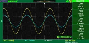
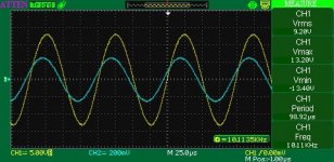
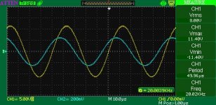
Below are pictures from 2-channel oscilloscope (2 KHz, 10 KHz, 20 KHz). Phase shift is clearly visible at 20 KHz, but it is not cause of oscillation because GNFB is disconnected.
1) GNFB disconnected - oscillation continues.
2) CFB disconnected - oscillation continues.
3) 0.22 uF capacitor connected between B3 (6N6P HV supply) and GND - oscillation waveform slightly changes.
4) Grid stoppers for 6N6P - quite difficult to install, sockets are soldered on PCB.
5) Removed input pre-driver 6N1P from the socket - oscillation continues (slightly different waveform, but 12 - 24 mV, around 67 KHz).
6) Removed 6N6P from the socket - oscillation gone, output noise around 4mV.
For tests I used the worst output transformer I have with leakage inductance 18 uH. Replacing it with better (9 mH leakage inductance) don't kill oscillation anyway. If amp will work with worst trafo, it will work with better one for sure. This unit is very large (around 4.5 kg), so stray capacitance should also be high.
All data below with GNFB disconnected.
Input voltage around 184 - 200mV.
Frequency / Output voltage 8 Ohm
20 - 9.00
200 - 9.60
2,000 - 10.00
5,000 - 9.60
10,000 - 9.20
15,000 - 8.60
20,000 - 7.80
25,000 - 7.20
30,000 - 6.60
35,000 - 5.88
40,000 - 5.00
Below are pictures from 2-channel oscilloscope (2 KHz, 10 KHz, 20 KHz). Phase shift is clearly visible at 20 KHz, but it is not cause of oscillation because GNFB is disconnected.
Attachments
Last edited:
Try to increase R24 to 3-4k. If oscillation continues after GNFB disconnected I suspect problem with feedback via power. Also you can try to run it without output tubes or with tubes closed by high bias. You need to see if there is any oscillation at the output of phase splitter.
Last edited:
If oscillation continues after GNFB disconnected I suspect problem with feedback via power.
Hmmm, how to to suppress it?
Hmmm, how to to suppress it?
Rethink power filtering. But first you need to find a stage which oscillates. First exclude output one by closing tubes.
Rethink power filtering. But first you need to find a stage which oscillates. First exclude output one by closing tubes.
Thanks, avp1. I have reduced idle current of output tubes tenfold. Oscillation continues, down from 12 - 20 mV to 4 - 8 mV.
Thanks, avp1. I have reduced idle current of output tubes tenfold. Oscillation continues, down from 12 - 20 mV to 4 - 8 mV.
If you can't close them completely, take them out.
If you can't close them completely, take them out.
I removed 6N6P phase splitter - oscillation stops. Is this enough to determine 6N6P as source of oscillation? I tried to take an oscillogram from the grid of output tube, looks like my oscilloscope have problem with DC (from BIAS supply).
I have soldered one leg (2nd go to oscilloscope probe) of 0.33 uF cap to R23 - grid stopper of output tube in order to isolate DC out of oscilloscope probe.
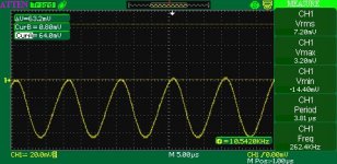
After all, its seems 6N6P long tail phase splitter is a source of spurious oscillation at at 2 frequencies.
Turning off amp cleans noise on oscilloscope screen - so this is oscillation from amp, not noise from any other device.
After all, its seems 6N6P long tail phase splitter is a source of spurious oscillation at at 2 frequencies.
Turning off amp cleans noise on oscilloscope screen - so this is oscillation from amp, not noise from any other device.
Attachments
Last edited:
Add g2-anode snubbers on output stage? UL often needs these.
LTP phase splitter can oscillate if input and output too near each other as one output is in phase with the input. Physically large caps make this worse.
LTP phase splitter can oscillate if input and output too near each other as one output is in phase with the input. Physically large caps make this worse.
Add g2-anode snubbers on output stage? UL often needs these.
LTP phase splitter can oscillate if input and output too near each other as one output is in phase with the input. Physically large caps make this worse.
Thanks, DF86.
What cap and resistor value would you recommend for anode-g2 snubbers?
Is there any trick to suppress oscillation at LTP?
I seem to recall 1k-few k plus 1-few nF. Generally, the largest resistor and smallest cap which kills the oscillation.
I cured LTP oscillation by inserting a grounded screen between in and out. The screen was just some bent thick copper wire. I did this because I had no scope to increase separation, which is always the first thing to do. Next time I use big caps (on the LTP output) I will allow more space for them!
I cured LTP oscillation by inserting a grounded screen between in and out. The screen was just some bent thick copper wire. I did this because I had no scope to increase separation, which is always the first thing to do. Next time I use big caps (on the LTP output) I will allow more space for them!
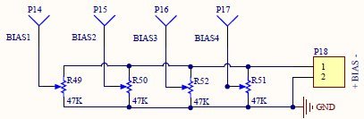
Your negative bias circuit...does it really not have any capacitance??? (Capacitors)
Power transformer, rectifiers and filters for HV B+ and BIAS are not shown (schematic is too obvious). BIAS supply have 500uF electrolyte and 0.22 uF film filter caps.
First increase R1 to 10-15k. Then try 330pf and 10k between plates of VL2. Then 1000pf capacitor with 1.5k resistor from B1 to plates of each output tube.
AVP1, are these mods to reduce phase shift between input/output signal and make GNFB more stable? Is there any formula in order to exactly determine these values of R and C?
Large transformer have quite high stray capacitance, so actually increasing it by 1000pF may lower resonant frequency of primary winding of the output transformer. Or am I wrong here?
- Status
- Not open for further replies.
- Home
- Amplifiers
- Tubes / Valves
- Stubborn Noise/Oscillation - Another Call for Help