Does National say they are matched?.........There's a small advantage in using 4780 for paralleling as both the amps are located in the same chip they are better matched than say paralleling two discrete 3886.
Which parameters are matched?
While NS doesn't state anything about the internals of the LM4780, from the work of Glenn Baddeley LM4780 Audio Power Amplifier - Glenn's Design Log we know that it is actually two independent regular LM3886 dice in one package.
Logistics alone make it quite likely that oftentimes the two dice will come from the same wafer, they might even be directly adjacent ones before depanelization, with rather small intrinisic process variations to expect. The common package will help to match further by keeping thermals in close/fast tracking.
Of course one shouldn't blindly rely on that kind of suspected matching and rather check actual values of offset, offset drift and, if possible, gain characteristics (use small signal pulse test).
Does National say they are matched?
Which parameters are matched?
While National doesn't specify anything, rather than trying to match different chips from different batches, I guess it's better if two chips from the same batch are put in one casing. The feeback bath and speaker outputs can also be kept matched if both the amps are in one package. I haven't done any tests actually to verify the parameters.
Sasmit,
I can conclude you just made up that bit of fiction.
which part ? The gain and offset parameters ? I never said I verified anything or Making the feedback path shorter and matching the speaker traces ? This is a very real problem that you would face if you were designing a parallel with 2 discrete chips. Using a single chip is definitely easier. I have a up and running amp which I listen to every day.
For such a small enclosure, you're going to need an intake fan (bottom of case blows air in, grille not required for computer fan, 80mm or 90mm at least) although you can use thermostat control if you like. To increase the effectiveness of underwhelming heatsinks, you'd have to speed them up considerably, and that needs a fan. Just exactly like computer CPU cooling the smaller the heatsink the faster (and louder) the fan.
Heatsinks, and transporting water are similar as for size and speed. Both the amount and the flow rate are important--either 1 leisurely trip with a big bucket or 900 trips with a teaspoon moving at mach 1 speed. Well, see a bigger enclosure would make things easier.
For using LM3886 without either burning down your house or under-volting far enough to make the output useless with nonstop spike limiter screeching, I'd favor Monobloc amplifiers, necessarily using 2 of those enclosures. And, yet both do need fans.
I'd rather see Solo TDA7295 amplifiers and a 15+15vac 6a transformer doing a lovely cool 40 watts per channel. The limiters in that model DO NOT SCREECH and thus under-volting works properly and it is pre-set at just about the point that may save your house from a fire. The odd model number will be harder to find, but TDA7295 is likely to be authentic. Of course, this still needs a fan if the amplifier enclosure is too tiny.
Would you consider a Class D amplifier kit? This does not remove the need of a fan to prevent overheat; however, your thermostat fan may run slower.
You'd need 105c caps, or actually I mean that you should avoid the 85c caps since they'd only last a maximum of 5000 hours in the lilliputian oven.
Also, be sure to check the transformer manufacturer's datasheet minimum clearance requirement, because if you get metal too close, the result is a lot of noise, lethal shock, fire and other annoyances common to dangerously small amplifier enclosures.
Last edited:
this partwhich part ?
is fiction !!!!!There's a small advantage in using 4780 for paralleling as both the amps are located in the same chip they are better matched than say paralleling two discrete 3886.
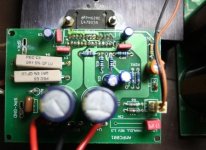
Ah, wait a minute. 38c? less than half the temperature of boiling water?I was testing the amp on a very small heat sink 100 X 100 MM with fins around 20 MM height, after playing for around 2 hours with ambient temperatures ~ 27C heat sink temperature was around 38C. I am not using a servo to correct the offset, I have an offset of around 12mV. . .
Well, that bears investigating.
Inverting mode or non-inverting mode?
Input load value if solo input or input loads value if dual?
What was the feedback resistors values?
And, what was the gain setting?
Got a schematic with that all on it?
What was the speaker load, 4 ohm speaker or 8 ohm speaker?
What was the rails voltages?
Any stability fine tuning?
Any specific power filtering for cleaner power?
It's in non inverting mode.
Speaker was a 4 ohm car audio unit ( Blaupunkt THx 542 ).
PSU rails are +- 28 volts.
The PSU board again is copied from a national application note on audio amp power supply design. I had around 20000 uF per rail of capacitance.
Input was from a TDA7449 based preamp,the datasheet mentions output resitance as 2k.
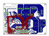
This is the schematic, the zobel resistor i used was 2.7 ohms although it is mentioned as 10 ohms in the schematic.
Attachments
Last edited:
Sasmit,
I can conclude you just made up that bit of fiction.
Andrew,
If you can have a look at what National's design support group replied to glenn on LM4780 related questions you can decide for yourself what's fiction what's not.
LM4780 Audio Power Amplifier - Glenn's Design Log
I wanted to check to see if there was some easy to find reason that the amp is remarkably cool. There isn't.
The only thing that I found is 10uF on both rails, which is quite similar to 4.7uF across the rails and either case removes some power noise. That helps a little bit, but not to the remarkable extent illustrated. However, this in addition to under-volting (28v rails) and good stability, should run that cool. Kudos!
Your offset is because of R6's high value (not enough input load). You could use 20k or 10k for lower offset. I also spotted the timer cap for the mute line seeking ground at signal star, but possibly it should have gone to power star instead of the input.
Unless C11 and C12 are (and remain) properly matched within a few %, there will be large cross-currents when the amp is hit with very low frequency signals.
Matching time constants is the main reason for DC-servos (by using precision film caps) in paralleled chipamps.
Things may get worse here because the cutoff of the input RC is lower than that of the feedback network, instead of the other way round.
Matching time constants is the main reason for DC-servos (by using precision film caps) in paralleled chipamps.
Things may get worse here because the cutoff of the input RC is lower than that of the feedback network, instead of the other way round.
and they don't claim that any of the parameters are matched.If you can have a look at what National's design support group replied to glenn on LM4780 related questions
Your story is complete fiction.
Unless C11 and C12 are (and remain) properly matched within a few %, there will be large cross-currents when the amp is hit with very low frequency signals.
Matching time constants is the main reason for DC-servos (by using precision film caps) in paralleled chipamps.
Things may get worse here because the cutoff [roll-off] of the input RC is lower than that of the feedback network, instead of the other way round.
For that amplifier would you recommend downsizing the input cap until the bass becomes cleaner, not necessarily less loud, just cleaner? The two amplifiers would have more in common that way, since there's only one input cap. Oh, and what would it be? 3.3u? 2.2u?
Instead of making the input cap too small, shouldn't the nfb cap values be increased by at least 220uF ((220u+3R)//47u//10n) so as to bypass the bass blocker with a larger capacitance value?
I'd put the roll-off of the feedback network at least one decade below the input roll-off (say, 1Hz vs 10Hz). This will result in large 'lytics ot large resistors. Another option would be to make the roll-offs identical, at some 1..10Hz corner freqs and then force the feedback legs to same relative AC potentials by placing a capacitor 10x the value accross. At start-up, until circuit parameters have settled, high currents might flow in either case, and the more capacitance you throw at the problem the longer this time period will be.
Of course you can just monitor the sharing resistor's current (at these freqs any AC multimeter will do) and watch for any cross current flow at 20Hz or so, with no load connected.
Of course you can just monitor the sharing resistor's current (at these freqs any AC multimeter will do) and watch for any cross current flow at 20Hz or so, with no load connected.
I'd put the roll-off of the feedback network at least one decade below the input roll-off (say, 1Hz vs 10Hz). This will result in large 'lytics ot large resistors. Another option would be to make the roll-offs identical, at some 1..10Hz corner freqs and then force the feedback legs to same relative AC potentials by placing a capacitor 10x the value accross. At start-up, until circuit parameters have settled, high currents might flow in either case, and the more capacitance you throw at the problem the longer this time period will be.
Of course you can just monitor the sharing resistor's current (at these freqs any AC multimeter will do) and watch for any cross current flow at 20Hz or so, with no load connected.
Although my schematic shows a 4.7uF input cap, if you see the pic of the test board I was using a 1uF input cap. With a 1uF input cap the roll off for the input and feedback are at the same point. Should I move the roll off of the input a decade higher than that of the feedback network. I am not facing any issue with the current values. May be this issue will crop up if I use the amp in a subwoofer kind of application ?
- Status
- Not open for further replies.
- Home
- Amplifiers
- Chip Amps
- improved LM3886 power amp from Shine7