for a general case nothing regal. I miss-stated it.
As long as the load impedance reflected to the driver is correct there should be no problem if the transformer is not a dual primary (CT) version like I'm using with the ct grounded.
Using the transformer I have wouldn't matter either if you left the ct floating.
I was think specifically about the Edcor WSM10K/600 that I must have been discussing in another thread.
OK, I had to test it since the minidac board is ready. I read through the configuration text and gave it a try in HW mode. With only USB connected the led2 gave light. I added power and all 3 shone. My PC found it as an USB Audio device. I chose 192khz and OSR pins accordingly and kept the FSEL pins open...
Silence... The only sound I get is a 2sec "Peeeeeeew" when I switch it off with the combined switch/potentiometer. I have tried the mute pins in every possible configuration without luck.
The rest of the pins are all open.
So this is my story - any successes out there?
Brgds
Silence... The only sound I get is a 2sec "Peeeeeeew" when I switch it off with the combined switch/potentiometer. I have tried the mute pins in every possible configuration without luck.
The rest of the pins are all open.
So this is my story - any successes out there?
Brgds
You may check the max samplerate supported ba PCM2707......
USB Audio - USB DAC - PCM2707 - TI.com
Thanks zinsula, I'm feeding it with 16/44.1 cd rate so it shouldnt be a problem.
Brgds
Post some pictures.
Yeah, right... How do I do that? Does insert image work or do I need to sign up at some other place and link afterwards? If the later forget it...
I'll give it a test though but it will take some time. Best luck ;-)
Brgds
Jepp, as I thought - insert url of my image... I don't want to do this....
Last edited:
Clickon "Go Advanced" below the quick reply text box. Then scroll down and select "Manaage Attachments" and it will allow you to upload photos, etc.
Clickon "Go Advanced" below the quick reply text box. Then scroll down and select "Manaage Attachments" and it will allow you to upload photos, etc.
Thanks TheGimp. I'll try that from the machine where I have tha photos probably tonight - if not tonight then tomorrow.
The best would be if someone pointed the finger on the problem...
Brgds
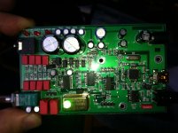
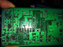
OK, here they come.
Hopefully they show up...
I can't se them. Well, actually I could 🙂 after submitting...
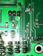
But anyway I can't figure out what you could find wrong in these pictures... They arn't of a quality where one could pinpoint anything from.
Now this was quite cool... I could take some closeups of your chosing with some lenses I have...
Brgds
Hopefully they show up...
I can't se them. Well, actually I could 🙂 after submitting...
But anyway I can't figure out what you could find wrong in these pictures... They arn't of a quality where one could pinpoint anything from.
Now this was quite cool... I could take some closeups of your chosing with some lenses I have...
Brgds
Attachments
Last edited:
Did you inspect the board closely before populating it? I found a short between traces on mine and removed it before I did any soldering.
Yes, I did. I noticed that many bypasses were not aligned and so forth... Not the top notch quality. Of course, I might have missed something. So TheGimp - yours is functioning?
Brgds
Brgds
I have also populated two boards from the first round, none of them functioned. After inspection, both had shorts on various points so it is not clear what is the status of the ICs. Did anyone manage to have a working board?
Last edited:
I'm getting ready to place my parts order and was wondering if a 10K load is necessary in place of the volume pot if the buffer is used, but not the headphone amp?
Replace the 47K (R28,R29) with 8.2K resistors?
What IC is used for the headphone amp?
Replace the 47K (R28,R29) with 8.2K resistors?
What IC is used for the headphone amp?
Has anyone tried the Nichikon KA series?
http://www.nichicon.co.jp/english/products/pdfs/ka_web_e.pdf
http://www.nichicon.co.jp/english/products/pdfs/ka_web_e.pdf
nope and when they promote it by saying things like this
nichicon make some really great caps and at a reasonable price too, but the audio grade stuff seems to me to actually be lower quality for more money
without further detail; it kinda turns me off.selected materials to create superior acoustic sound
nichicon make some really great caps and at a reasonable price too, but the audio grade stuff seems to me to actually be lower quality for more money
Parts due in Friday. Mouser shipped the same day I ordered.
I got a link from EDN today to an interesting article for those of you (like me) trying to come up to speed on data conversion.
Audio converter subsystem design challenges in the 21st century - 2011-12-06 22:16:39 | EDN
I got a link from EDN today to an interesting article for those of you (like me) trying to come up to speed on data conversion.
Audio converter subsystem design challenges in the 21st century - 2011-12-06 22:16:39 | EDN
- Status
- Not open for further replies.
- Home
- Source & Line
- Digital Source
- High Performance WM8741 Upsampling DAC New Version build thread (show 'n tell too)