Thanks for the comments guys.
You do realize there is no one-size-fits-all-and-everybody-is-happy enclosure; though we did go for the one-size-fits-most. 😉
When deciding dimensions we took everything into consideration and we also examined various alternative designs like the ones proposed.
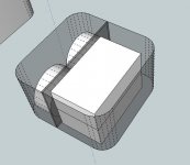
We settled for this cube-like 3U design for various reasons.
It's short enough to fit in most racks/shelves but also tall enough to not look funny or "lost" when you place it on the floor next to your loudspeakers (where monoblocks actually make more sense).
It's small enough to fit a monoblock amp/smps without looking empty but also large enough to fit 3 (maybe more) channels with a clever arrangement and utilization of the added flexibility the height and panels provide. I've even managed to fit a dual mono amp (2xNC400s, 2xSMPS600s) inside, but I bet wiring will be a challenge on that one!
Moreover, it's ratio of height to width/depth in conjunction with it's curvy design make for an aesthetically pleasing, unique enclosure.
These are all advantages that come from the added height, which, IMHO proves it's not really "wasted space".
There are plenty of enclosures out there for someone who wants a 450x300x60 or something more..ordinary - though I doubt you can fit that much more stuff in it (plus these will indeed look empty and a waste of space if you try and use them for a single monoblock amp).
Last but not least, me and my friends like it more than any alternative. 😱
Remember that we originally picked this for our own use and we just have a few to "spare" - of course there are more than a few available in case there is enough interest.
Please take the time to draw a quick sketch and play around.
Internal dimensions are 184x184x112mm and you can find the dimensions of the Hypex modules in the respective datasheets.
Also create a mock enclosure out of paper or something at 200x200x120mm. You'll see it's actually really small for the stuff you can fit in it.
I'll ask SilliconRay regarding the option of having them anodized in black upon request (perhaps with a small surcharge).
You do realize there is no one-size-fits-all-and-everybody-is-happy enclosure; though we did go for the one-size-fits-most. 😉
When deciding dimensions we took everything into consideration and we also examined various alternative designs like the ones proposed.
We settled for this cube-like 3U design for various reasons.
It's short enough to fit in most racks/shelves but also tall enough to not look funny or "lost" when you place it on the floor next to your loudspeakers (where monoblocks actually make more sense).
It's small enough to fit a monoblock amp/smps without looking empty but also large enough to fit 3 (maybe more) channels with a clever arrangement and utilization of the added flexibility the height and panels provide. I've even managed to fit a dual mono amp (2xNC400s, 2xSMPS600s) inside, but I bet wiring will be a challenge on that one!
Moreover, it's ratio of height to width/depth in conjunction with it's curvy design make for an aesthetically pleasing, unique enclosure.
These are all advantages that come from the added height, which, IMHO proves it's not really "wasted space".
There are plenty of enclosures out there for someone who wants a 450x300x60 or something more..ordinary - though I doubt you can fit that much more stuff in it (plus these will indeed look empty and a waste of space if you try and use them for a single monoblock amp).
Last but not least, me and my friends like it more than any alternative. 😱
Remember that we originally picked this for our own use and we just have a few to "spare" - of course there are more than a few available in case there is enough interest.
Please take the time to draw a quick sketch and play around.
Internal dimensions are 184x184x112mm and you can find the dimensions of the Hypex modules in the respective datasheets.
Also create a mock enclosure out of paper or something at 200x200x120mm. You'll see it's actually really small for the stuff you can fit in it.
I'll ask SilliconRay regarding the option of having them anodized in black upon request (perhaps with a small surcharge).
Attachments
Has anyone found a good solution for attaching thick speaker wires into the nCore speaker terminals? I tried dividing a 4mm wire into two equal sized sections, but i could not make the connection as reliable i would've liked. I still could get the wire out with very little force.
I guess, Small gold plated forks that are squeezable (with a tool) on top of wire would be perfect.
Currently i am using regular 1.5mm connector wire.
I formed the wire like a fork, like in the image before and then kept the wires quite long so they stuck out on the other side of the connector. Then it wasn't possible to pull out the wires.
Hi Guys,
Fwiw, UcD400HG+HxR setup going up for sale (for obvious reasons 🙂):
http://www.diyaudio.com/forums/swap...-monoblocks-electronics-only.html#post2923090
Regards
Fwiw, UcD400HG+HxR setup going up for sale (for obvious reasons 🙂):
http://www.diyaudio.com/forums/swap...-monoblocks-electronics-only.html#post2923090
Regards
I am encountering the same problem as ZAP4EVER did with my ncores. I have everything connected and when I power it up the LEDs on the amps lit up but there was no sound.
I wired it as following:
correct me if I'm wrong, but this is the same as in the manual, figure 3 on page 12.
There is one more thing I don't understand. Page 5 of manual (7.3 J9 audio input) says that pin 4 (amp) may be used to attach the shield of a shielded twisted pair cable, but the
“audio ground” connection of an unbalanced source should never connect here.
This implies that that...... Oh heck, as I'm writing this I think I figured out what I did wrong. I connected the ground (amp pin 4) to the the XLR (pin 1). It probably should not be connected at all when using a unbalanced source. I was probably working on it for to long and missed this completely.
Well that changes my question: Should the ground of the amp (pin 4) be left floating? I would be grateful if if someone could answer that, because I do not want to to connect it all again to figure out that it still doesn't work.
-----
Regards,
Corpius
I wired it as following:
- pin 1 (amp analogue in non inverting) to pin 2 (XLR)
- Pin 2 (amp analogue in inverting) to pin 3 (XLR)
- Pin 3 (amp nAMPON) to pin 1 (XLR)
- pin 4 (amp ground) to pin 1 (XLR)
- Signal (RCA pin) to pin 2 (XLR)
- ground (RCA shell) to pin 3 (XLR)
- The shield of the microphone cable it soldered to the RCA shell (same as ground) and to pin 1 of the XLR connector.
correct me if I'm wrong, but this is the same as in the manual, figure 3 on page 12.
There is one more thing I don't understand. Page 5 of manual (7.3 J9 audio input) says that pin 4 (amp) may be used to attach the shield of a shielded twisted pair cable, but the
“audio ground” connection of an unbalanced source should never connect here.
This implies that that...... Oh heck, as I'm writing this I think I figured out what I did wrong. I connected the ground (amp pin 4) to the the XLR (pin 1). It probably should not be connected at all when using a unbalanced source. I was probably working on it for to long and missed this completely.
Well that changes my question: Should the ground of the amp (pin 4) be left floating? I would be grateful if if someone could answer that, because I do not want to to connect it all again to figure out that it still doesn't work.
-----
Regards,
Corpius
Last edited:
What the second photo shows is
J9 Pin 1 (=red wire) connects to centre pin of RCA.
J9 Pin 2 (=white wire) connects to outer part of RCA.
J9 Pin 3 (separate black wire) connects to outer part of RCA (optionally via switch to allow mute/unmute but you can connect it directly as well).
J9 Pin 4 (braided shield around the red and white wires) connects to outer part of RCA.
Now, when you build the whole thing into a stereo chassis, please remove the white insulating material from the RCA. It has to make contact with the chassis (see figure 4). For mono chassis or for "zero chassis" it is less critical but still a good idea to insure solid contact between RCA and chassis. When using RCA, do not connect mains earth to chassis as well. If you do want to connect mains earth, you're down to the more complicated version of figure 5.
@Arend-jan, I tried to make those "this wire goes here" drawings, they are figures 2, 4 and 5. Is there something I could improve there as well?
I just read Bruno´s post where he says that pin 4 (amp ground) should be connected to the outer part of the RCA when using RCA connectors in stead of XLR. This is the same as the audio ground.
????????
So this is not the same as the manual says. It says says that pin 4 (amp) may be used to attach the shield of a shielded twisted pair cable, but the
“audio ground” connection of an unbalanced source should never connect here.
There might be another case option but unfortunately I can't say too much yet. I've been working on a few designs and think I've decided on a favourite. I have drawings but can't use CAD (I've just obtained some CAD software so might have a go but it isn't something quick to learn). It would be a monoblock design in a more traditional enclosure but with a high quality thick walled box and a heavily customised faceplate. There is a guy off here who is looking into whether he can manufacture it exacty as I would want at a reasonable price. If he can then great. If he can't then I will be talking to an engineer I know and/or Siliconray. I want the rear plate just to have an XLR input and possibly two sets of binding posts (and power of course). The front will probably have an illuminated switch but might otherwise just have an LED. There might be an RCA option.
I have looked at lots of off the shelf enclosures and resulting internal layouts. One pretty compact one does work but I have decided that I would prefer a bespoke size if viable as although I don't want it to have loads of free space, I don't think it's a good idea to have the two modules almost touching each other either and this is the impression I get having been in correspondence with Hypex over a number of matters.
The currently favoured design would be 167x67x300, with a larger faceplate taking it to about 187x77. Wall thickness would be 6mm all around but with a 15 mm faceplate (at the thickest point).
I would be quite happy just getting my own but it might be the case that I need to get say 10 or more made for it to be viable. If anyone is interested and wants to know more, feel free to get in touch by pm. I can't make any promises on this one as yet though but it might be a nice alternative to the square design above.
I am at the stage of finding out whether the guy I've been discussing it with so far, who would want to make several and sell them, can make it as I want. If so then great. If not then I will try elsewhere. If anyone is interested
I've contacted two companies for prices for cases that should fit 2 modules and 2 PSUs.
First one is called PRAL-22307 All Alum. Chassis and it's under High grade chassis for amp section:
Chassis case item
The dimensions are 22cm(W) x 30cm(D) x 7 cm(H).
The other one is listed under part no. as two from the top (
HY 70-28-2):
http://www.takachi-enclosure.com/data/pdf/en2011_109.pdf
Dimension here are 280mm (W) x 231mm (D) x 70mm (H)
This one needs to be modified where width becomes depth and depth becomes width, in order to get the heat sink plates on the side. Shouldn't be a problem I would think.
Looking forward to hear what they cost.
I had a quote on the PRAL15307C enclosures with the curved face but the dimensions aren't quite right.
The price for two was £238 posted to the UK excluding VAT and duty.
The PRAL-22307 is fine but still needs a lot of customisation to look anything special (imo).
Regarding bi-wiring (and it may be on here somewhere already but I can't find it) is it better to have two sets of external binding posts with two sets of wires to the board or one set and use forked connectors for one set of LS cables and plugs for the other?
bruno would probably remind us all of using 4-pole neutrik speakons. Ive decided against that and use 2 sets of normal connectors per amp for "backwards compatibility".
And 2 sets of cables to the board, yes. Whether that really matters on such a small signal length I dunno, but I just like the idea...
And 2 sets of cables to the board, yes. Whether that really matters on such a small signal length I dunno, but I just like the idea...
Speakons are new to me. I shall be making my own LS cables so I could go down that route. I was planning on two sets of posts and two sets of wires inside but the discussions on thick wires inside got me wondering whether this is a good idea. What size forks are needed for the internal NC400 connections by the way and if biwiring inside would you just put both wires into one fork?
I agree. It seems to be step above Modushop's, but perhaps not worth the extra cost.The PRAL-22307 is fine but still needs a lot of customisation to look anything special (imo).
http://www.modu.it/frontale_nero.jpg
Seems like we can't decide on something custom though. I don't want four cases when I can get away with two.
I think what will happen from my perspective is that I will pursue my current design and if successful in getting it built, the builder will then have the option to offer them to others but if they don't want to I'll just pass on the design to others to use if they want. However if there is a minimum needed to make it viable I will see if anyone's interested.
My view of this is that the case is the main respect in which this is DIY so I would get satisfaction from having something built to a design over which I have at least had some influence.
Originally I had sourced rear cases in line with those from Modushop but better dimensions and was just going to get custom face and back plates made but ideas have moves on from there and I'm hopeful of getting a bespoke design made.
I just read Bruno´s post where he says that pin 4 (amp ground) should be connected to the outer part of the RCA when using RCA connectors in stead of XLR. This is the same as the audio ground.
????????
So this is not the same as the manual says. It says says that pin 4 (amp) may be used to attach the shield of a shielded twisted pair cable, but the
“audio ground” connection of an unbalanced source should never connect here.
I find this very simple thing very complicated to explain... What I'm saying is not that they can't somehow be connected (in unbalanced systems they always end up connected) but that you should not do the "obvious" thing (tying pins 2 and 4 together at the module to get a "simple unbalanced input", that would be wrong, so wrong).
Last but not least, me and my friends like it more than any alternative. 😱
Remember that we originally picked this for our own use and we just have a few to "spare" - of course there are more than a few available in case there is enough interest.
Being involved in the designing of this case I would like to mention that
this is a unique chance to get a really special case at an excellent price.
It is both aesthetically pleasing and multifunctional. It suits the majority
of the needs and can be easily placed on the side of a speaker - maybe
the next best place performance-wise after inside the speaker.
For those concerned about the adjacent placement of nCore modules in
the multichannel layout, there is just no problem. I think Bruno may
reassure it, and our many years experience with the UcD modules is
definitely positive (we have used up to 5 UcD400 in a row with minimal
spacing between them). Nevertheless just wait for the final quote and
choose the case you think that nCores deserve.
I find this very simple thing very complicated to explain... What I'm saying is not that they can't somehow be connected (in unbalanced systems they always end up connected) but that you should not do the "obvious" thing (tying pins 2 and 4 together at the module to get a "simple unbalanced input", that would be wrong, so wrong).
But with my setup with a non-balanced source to I should not connect pin 4 (module) to anything. Just like Figure 3 in the manual (RCA to XLR). Right?
What's the point of having an amp close to the speaker? Do you actually believe that longer cables with have an impact on the sound?
I too will be placing the amps next to the speakers however I want an enclosure that will look good if placed that way or not. If I was thinking of functionality alone I would have the power at the back (and inputs) and output at the from in which case a square design would be fine.
It's helpful to know about the module placement. It was just that in squeezing the modules and leaving enough room for the switches, speaker bindings etc and connections internally, they would have been a couple on mm apart. The bespoke layout gives a bit more room but not excessively so.
It's helpful to know about the module placement. It was just that in squeezing the modules and leaving enough room for the switches, speaker bindings etc and connections internally, they would have been a couple on mm apart. The bespoke layout gives a bit more room but not excessively so.
with regards to speaker wire length, is it better to have short speaker wire by placing the amp near the speaker and have long balanced xlr interconnects or short interconnects and long speaker wire?
I too will be placing the amps next to the speakers however I want an enclosure that will look good if placed that way or not.
That's the issue with 1U and "1.5 U" (60-65mm) enclosures.
They "disappear" or look plain funny if you place them on the floor next to a loudspeaker.
If I was thinking of functionality alone I would have the power at the back (and inputs) and output at the from in which case a square design would be fine.
True.
If only I wasn't so vain about showing off my NCore monoblocks, I'd go that way as well. 😀
What's the point of having an amp close to the speaker? Do you actually believe that longer cables with have an impact on the sound?
Assuming a balanced source and amplifier (as is NCore with its carefully designed input stage and whatnot), shortest possible speaker cables and long interconnects is the optimal way to go. I think Bruno will agree this (I'm 99% certain he's mentioned it before).
- Status
- Not open for further replies.
- Home
- Amplifiers
- Class D
- Hypex Ncore